Constructing a 3D Printer [Prusa I3]
SECTION 5 - Electronics - Page 1
Section 1 - Wooden frame : part 1 - part 2 - part 3Section 2 - Y Axis : part 1 - part 2 - part 3
Section 3 - X-Z axis : part 1 - part 2
Section 4 - Extruder : part 1 - part 2 - part 3
Section 5 - Electronics : [[ part 1 ]] - part 2 - part 3
Section 6 - Coarse Calibration & Software : part 1 - part 2 - part 3
Section 7 - Fine Calibration & Software : part 1 - part 2 - part 3
Section 8 - Extras : part 1 - part 2 - part 3
Section 9 - Maintenance & Modding : part 1 - part 2
LETHAL VOLTAGES INVOLVED. I DO NOT TAKE ANY RESPONSABILITY FOR ANY DAMAGES. PROCEED WITH CAUTION
We need a schematic in order to construct our printer.The schematic can be found below :

We unbox our power supply (S-250-12 5V / 20A MAX)
Select your input voltage (220/110V). In Europe we use 220V.
Front view of the power supply :
For security reasons we have to make a front cover for our power supply.
We need :
3 pieces 165x20x10mm for the front panel
2 pieces 60x20x10mm for the legs
1 piece 145x20x10mm for the top
1 piece 165x20x10mm for the top part 2
10 M3 woodscrews 20 mm long
Wood glue
The schematics can be found here [open the dxf with LibreCAD]
In order to open the included 3D Model use FreeCAD.
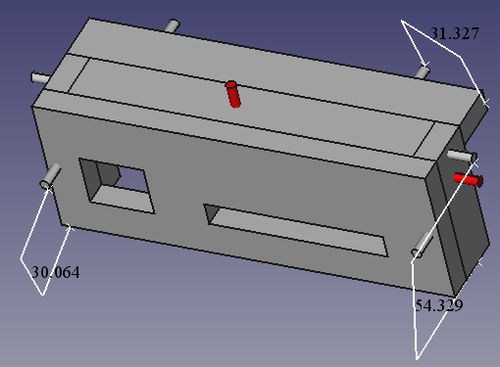
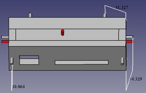
Assemble the front mask like below :


The three red cylinders indicate the screws that fix the mask on the power supply.
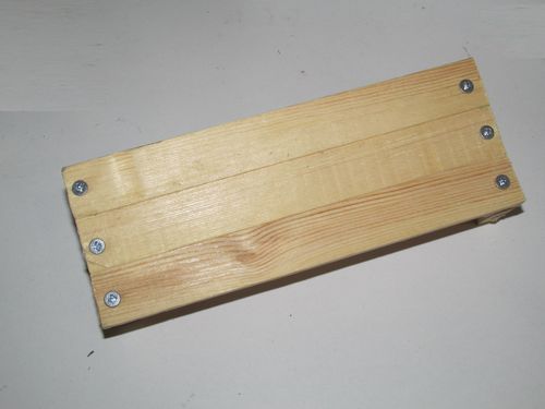
Glue the panel using clamps
Put the screws on the front

Lateral view :
Back view :
Finished panel :
Notice this is another panel but the design is the same.
Make the two front cuts using a drill and a rasp.
Cut 4 pair-wires like the photo below. (60cm up to 1 meter each)
You have to mark the negative pole of each pair.
The negative pole is marked with a black strip
Use a multimeter if you are not sure.
Place the wires.
Notice two pairs are in parallel (used for the heatbed).
The forth pair is indicated by the red and black line.
Now cut your 220V cable carefully
We are using a rocker DPST switch with light. Model KCD4-201N 4 Pin ON/OFF 2 Position.
Rated : 16A/250V AC, 20A/125V AC
Grind the legs of the 220V switch
Place the switch into the panel and solder the 220V switch with the power cord.
Use heatshrink tubes in order to isolate the live connections.
Notice that this kind of switch has polarity in order to function correctly the led.
Pass the 12V cables through the slot (4 pairs).
Double-check the polarity of the 220V cables and of the switch.
Shrink the heatshrink tubes. Or isolate using hotglue.
Now screw the 3 pairs into the Ramps 1.4 jack like the photo below .
Notice that the black sign is the negative pole.
Notice again that the left line (11A) has two parallel cable pairs.
IMPORTANT Double/triple check your 220V and 12V connections :

Screw the wooden mask into your power supply.
The final result of our power supply :
Add a 80mm fan over the top using zip ties.
Fix the 220V power cable with zip ties also on the power case.
Use the forth cable pair in order to power the fan.
CAUTION re-check everything before pluging the power supply into the mains.
Make sure that the 12V cables are not shorted. Test the power supply using a multimeter :
If you get 12 - 12.5 V you are good to go .
If you are way off then shut down the power, remove the plug from the mains, unscrew the wooden mask and adjust the trimpot with a screwdriver shown below :

Do not adjust this trimpot with the mains plugged.
Notice that the power fan should work.
In the next part we will see how to connect Ramps in our system.
Section 1 - Wooden frame : part 1 - part 2 - part 3
Section 2 - Y Axis : part 1 - part 2 - part 3
Section 3 - X-Z axis : part 1 - part 2
Section 4 - Extruder : part 1 - part 2 - part 3
Section 5 - Electronics : [[ part 1 ]] - part 2 - part 3
Section 6 - Coarse Calibration & Software : part 1 - part 2 - part 3
Section 7 - Fine Calibration & Software : part 1 - part 2 - part 3
Section 8 - Extras : part 1 - part 2 - part 3
Section 9 - Maintenance & Modding : part 1 - part 2