Constructing a 3D Printer [Prusa I3]
SECTION 1 - Wooden frame
Section 1 - Wooden frame : [[ part 1 ]] - part 2 - part 3Section 2 - Y Axis : part 1 - part 2 - part 3
Section 3 - X-Z axis : part 1 - part 2
Section 4 - Extruder : part 1 - part 2 - part 3
Section 5 - Electronics : part 1 - part 2 - part 3
Section 6 - Coarse Calibration & Software : part 1 - part 2 - part 3
Section 7 - Fine Calibration & Software : part 1 - part 2 - part 3
Section 8 - Extras : part 1 - part 2 - part 3
Section 9 - Maintenance & Modding : part 1 - part 2
Last update: 06/11/2018
In this series of tutorial i will describe how to construct a Prusa I3 3D printer from scratch.
There are a lot of tutorials in reprap official site but i think that the Prusa I3 model is not covered enough.
Prusa I3 is at my opinion the best solution [in 2015] for a beginner to start.
I will start this tutorial assuming that you want to make a simple but stable machine.
So with that in mind i have selected a single extruder version with a wooden frame in order to keep the cost as low as possible.
If you are in a rush then these series of tutorials are not for you.
We will split this tutorial into sections.
I recommend that each section is a dedicated day.
Only a step by step approach will keep you in the right path in order to construct this machine.
If you think that in an afternoon will make this machine is better that you do not start at all.
This is valid even if you buy a full kit.
I do not recommend to buy an already assembled machine since the machine once arrives at your home needs calibration.
Also you have to understand how to assemble an extruder since you will change it.
Even more once you made a machine like this you have no fear of maintenance since you know "everything" about this machine . So at least to me an fully pre-assembled machine does not make sense at least for now.
Let's start with our wooden frame. The wooden frame is the most important part.
In these series we offer two ways making the wooden frame.
The second (alternative) way is simpler to build but looks less attractive can be found at part 3 of the section 1.
You have to make it right else you are compromising heavily your printer. Take you time into this step .
BOM - Wooden frame:
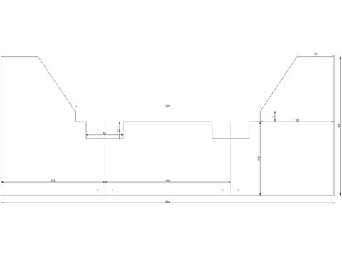
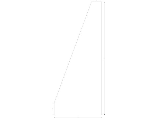
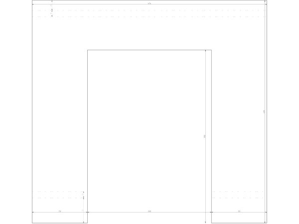
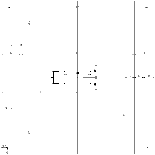
- Plywood 12 mm think (marine grade) [Schematics in LibreCAD]
- 170cm wooden stick 2 cm x 2 cm
- 48cm wooden stick 2 cm x 1 cm (or better 60cm)
- 40x M3 wood screws 25 mm length
- Wood glue
Notice that LibreCAD can print 1:1 dxf files easily by using "File" -> "Print preview" -> "1:1"
The dxf files are in mm.
The bottom frame :

The two legs :

The vertical frame :

The moving tray :

Once you have done cutting the frame then cut the 2x2 cm wooden sticks into :
- 2x 7 cm
- 2x 16 cm
- 2x 41,5 cm
- 1x 41 cm
- 6x8 cm equal parts (or even better 6x10 cm)
Please remember that from a plane pass three points.
Please do not skip this pass it is important !
Section 1 - Wooden frame : [[ part 1 ]] - part 2 - part 3
Section 2 - Y Axis : part 1 - part 2 - part 3
Section 3 - X-Z axis : part 1 - part 2
Section 4 - Extruder : part 1 - part 2 - part 3
Section 5 - Electronics : part 1 - part 2 - part 3
Section 6 - Coarse Calibration & Software : part 1 - part 2 - part 3
Section 7 - Fine Calibration & Software : part 1 - part 2 - part 3
Section 8 - Extras : part 1 - part 2 - part 3
Section 9 - Maintenance & Modding : part 1 - part 2