Constructing a 3D Printer [Prusa I3]
SECTION 3 - X Z axis - Page 1
Section 1 - Wooden frame : part 1 - part 2 - part 3Section 2 - Y Axis : part 1 - part 2 - part 3
Section 3 - X-Z axis : [[ part 1 ]] - part 2
Section 4 - Extruder : part 1 - part 2 - part 3
Section 5 - Electronics : part 1 - part 2 - part 3
Section 6 - Coarse Calibration & Software : part 1 - part 2 - part 3
Section 7 - Fine Calibration & Software : part 1 - part 2 - part 3
Section 8 - Extras : part 1 - part 2 - part 3
Section 9 - Maintenance & Modding : part 1 - part 2
Bill of materials for this part :
2x 470mm M8mm smooth rod for the X axis
2x 400mm M8mm smooth rod for the Z axis
2x 375mm M5 threaded rod for the Z axis
3x stepper motors 42BYGHW811 [one for the X axis , two for the Z axis] with current rating 2.5A
Alternatively you can use the 42BYGHW804 with current rating 1.2A
1x M8 bolt 30mm
1x M8 nut
7x M3 25mm for plastic clamps
8x M3 bolts 30mm [ 2x for "x arm" + 6x for endstops]
15x M3 nuts
15 x M3 10 mm [6x Z axis motors + 6x Z axis coupler + 3x X axis motor]
2x M5 nuts
8x M3 20mm wood screws [for Z axis]
7x lm8uu bearings
1x 608zz bearing
2x 625zz bearings for the z axis
1x GT2 20 teeth pulley
1x GT2 Timing belt 1m x 6mm
2x 5mm x 5mm couplers
Recommended : "Z-M5-Kurl-Coupler.stl". This coupler is included at x-z-axis-stl file located below.
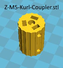
Coupler also recommended : ebay
Not recommended coupler : Prusa durable z-axis motor coupling [ReprapWorld]
1X bearing-guide_brnrd

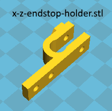
2X x-z-endstop-holder new model with two holes

1x x-arm
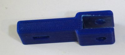
1x x-carriage
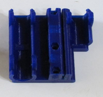
1x x-end-left.stl and 1x x-end-right.stl
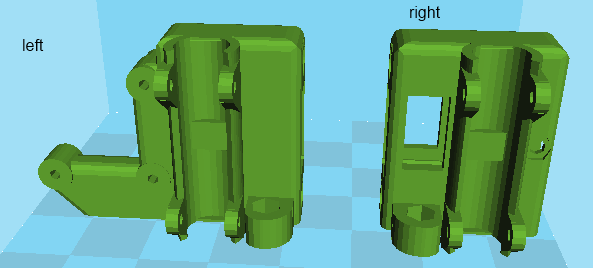
1x z-axis-bottom-left.stl and 1x z-axis-bottom-right.stl
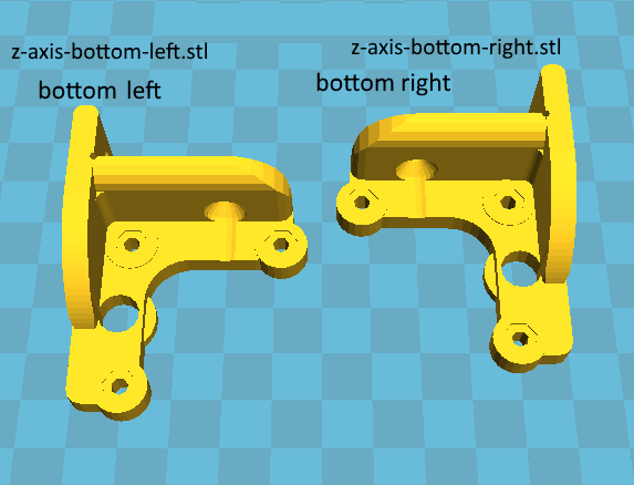
1x z-axis-top-left-with-bearing-M8Rods.stl and 1x z-axis-top-right-with-bearing-M8Rods.stl
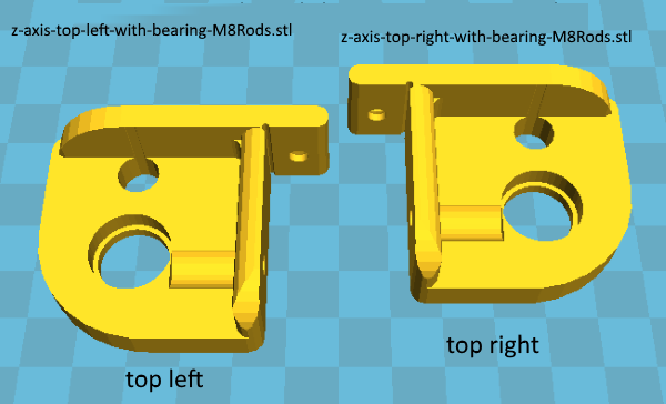
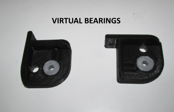
2x VirtualBearing625.stl if you do not have two the 625zz bearings
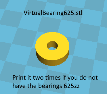
Alternatively for the z axis-old : 1x z-axis.stl (older version without top bearings not recommended any-more located at OLD/z-axis.stl obsolete)
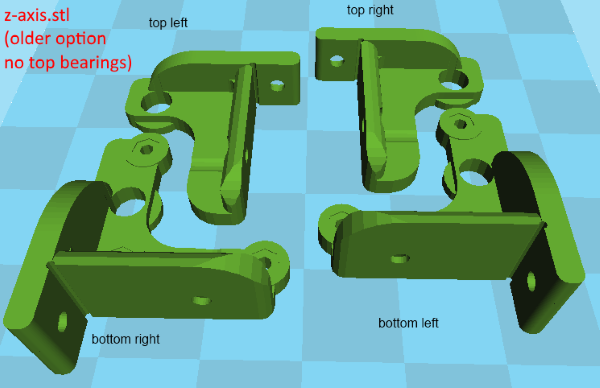
Download all stl files of the X-Z axis here : x-z-axis-stl
The z-axis top part can be also found at thingiverse
Let's start building our X-Z frame.
Insert the seven lm8uu bearings into the "x-carriage", "x-end left" and "x-end right" plastic objects like the photo below.
Now with the help of seven 25mm M3 bolts and nuts we secure our bearings like the photos below :
Now place the 608zz bearing into the bearing guide
Use the M8 30mm bolt as axis of the bearing.
Make sure that the bearing is rotating freely, if not, grind the "x arm". The newer version of the x-arm should not have any issues of this kind.
Cut the two small bridges of the "x end right" object.
File the gap like below in order to insert freely the "x arm"
The correct horizontal order of the three x axis objects is shown below :
Screw the pulley into the motor using the two hex screws
Please ignore for now the GT2 belt shown into the photo.
Now fix the motor using three M3 10 mm bolts with the "x end left" object.
Using a M8 drill bit clean the four holes of the "x end left" and "x end right".
Now insert the two M5 nuts one into the "x end left" and one into the "x end right".
Using a M8 drill bit clean the holes of the top and bottom Z axis plastic parts.
New version of the z-top part :
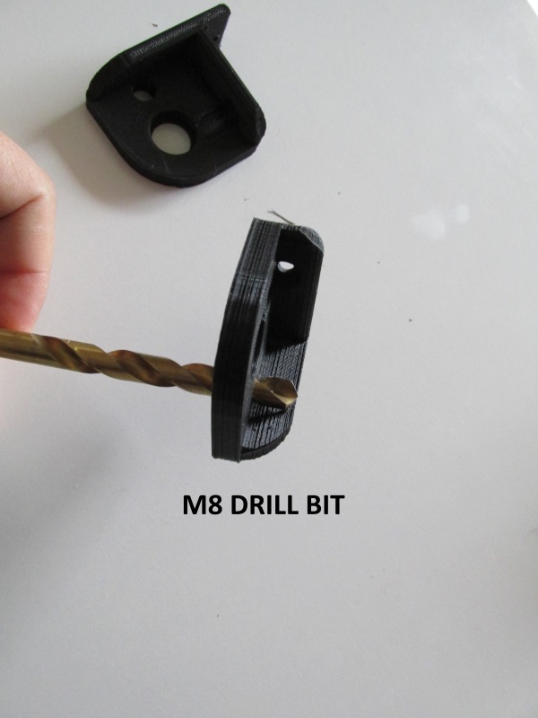
For the new z-top coupling version :
If you have the two 625 bearings just place them at the top part like the picture below :
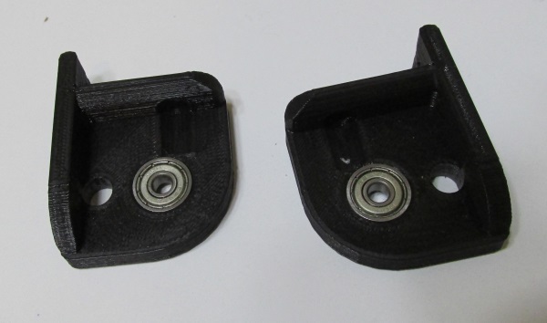
If you do not have the two 625 bearings use a M5 drill bit in order to clean the hole of the Virtual plastic bearings and fit them to the top part.
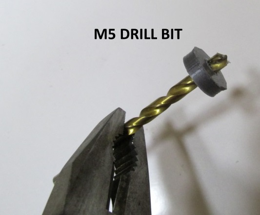
Older version of the z-top part :
Snap the excess plastic at the "z axis bottom" objects.
Assemble the parts like the picture below.
Start with the X axis using the two 470mm M8mm smooth rods and then pass at the Z part using the two 400mm M8mm smooth rods.
Do not place yet the two M5 threaded rods.
Also pay attention at the direction of x carriage.
Remember to screw with six M3 10 mm bolts the two Z motors into the "z axis bottom" plastics.
Now rotate the x-z frame gently and place it into your wooden frame. (90 degrees rotation from horizontal to vertical).
Do not put any wood screws yet.
If you have two ebay "5mm x 5mm" couplers then fix them into the two Z motors.
Unfortunately i had two couplers like this.
So i had to make a 2.5mm top hole and i had to add threads with a thread mill on both of mine couplers.
Take a look at the photo below.
Using the two bottom screws (im my case two 10mm M3) place the coupler into the motor.
Now pass (screw) the M5 rod from the top to the bottom.
Do this on both of the Z axes.
Now secure the couplers by screwing the top screws . Into my case i had to screw only one top screw for each coupler (M3 10mm bolt).
Another great way to connect the stepper motors with the "Z-M5-Kurl-Coupler.stl" presented below :

Use six M3 bolts 8mm long and six M3 nuts for each coupler.
The stl for this z-coupler can is included at "x-z-axis-stl" zip file.
Below you can find some photos from this coupler used in a newer machine.
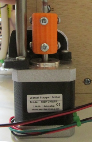
Here is the hole structure :
Below is a newer machine using the knurled couplers in grey and z-top couplers in red :
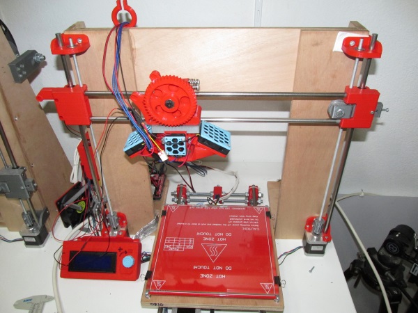
A machine using the knurled couplers in orange :
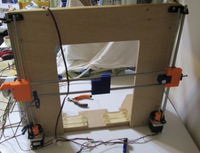
Below is a machine using the new z-top couplers in black :
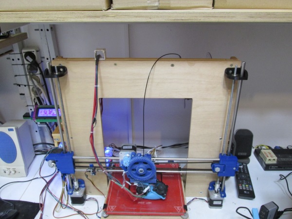
In the second part we will see how we fix the X-Z frame with our wooden frame.
Section 1 - Wooden frame : part 1 - part 2 - part 3
Section 2 - Y Axis : part 1 - part 2 - part 3
Section 3 - X-Z axis : [[ part 1 ]] - part 2
Section 4 - Extruder : part 1 - part 2 - part 3
Section 5 - Electronics : part 1 - part 2 - part 3
Section 6 - Coarse Calibration & Software : part 1 - part 2 - part 3
Section 7 - Fine Calibration & Software : part 1 - part 2 - part 3
Section 8 - Extras : part 1 - part 2 - part 3
Section 9 - Maintenance & Modding : part 1 - part 2