Constructing a 3D Printer [Prusa I3]
SECTION 2 - Y axis - Page 1
Section 1 - Wooden frame : part 1 - part 2 - part 3Section 2 - Y Axis : [[ part 1 ]] - part 2 - part 3
Section 3 - X-Z axis : part 1 - part 2
Section 4 - Extruder : part 1 - part 2 - part 3
Section 5 - Electronics : part 1 - part 2 - part 3
Section 6 - Coarse Calibration & Software : part 1 - part 2 - part 3
Section 7 - Fine Calibration & Software : part 1 - part 2 - part 3
Section 8 - Extras : part 1 - part 2 - part 3
Section 9 - Maintenance & Modding : part 1 - part 2
Let's see what we will need in order to build the y axis.
BOM for the Y Axis:
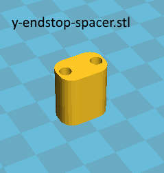
2x1 cm length 1cm wood stick spacer for the endstop or the "y-endstop-spacer.stl" that can be downloaded below.
2x M8 smooth rods length 370mm
2x M10 threaded rods length 400mm
4x M8 threaded rods length 220mm
12x M10 nuts
12x M10 washers
23x M8 nuts
26x M8 washers
4x M3 washers [for the heatbead]
1x M8 bolt 30mm
1x 608zz bearing
1x 42BYGHW811 stepper motor with current rating 2.5A.
Alternatively you can use the 42BYGHW804 with current rating 1.2A
1x GT2 20 teeth pulley with Bore 5mm
1x GT2 Timing belt 1m x 6mm width
1x heatbed 214 mm x 214 mm
1x glass 20,25 x 21,5 cm of 4 mm thickness
4x 15 mm binder clips
8-10x M3 20mm wood screws [3x2 y bushing + 2-4x y belt holder]
2x M3 10mm bolts [motor]
10x M3 30mm bolts [3x bushings + 1x drive train + 3x heatbed + 3x endstop]
1x M3 40mm bolts [1x heatbed]
11x M3 nuts
2x springs 25mm length 10mm diameter or 4x 23mm length 9mm diameter
1x Mechanical endstop mini switch
1x end stop cable (three wire cable : red/black/yellow)
100x cable ties 3x100 mm
4x y-axis-bracket-M10
Important info : these brackets won't be used at this stage of tutorial but you need them once you have done the X-Z plane. So keep them apart for now. Do not try to fix the y axis with the wooden frame at this stage !
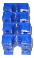
4x y-axis-corner20-ziptie or 4x y-axis-corner22-ziptie
The top small hole is used in order to fix the top linear rod with a zip tie.
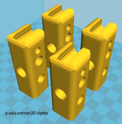
Notice that if you have constructed the alternative wood frame then you should print the "y-axis-corner22-ziptie.stl" instead
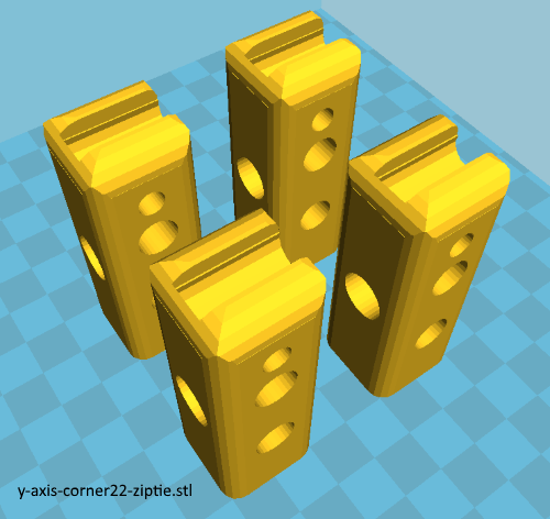
Older obsolete version y-axis-corner-long located at OLD/y-axis-corner-long.stl
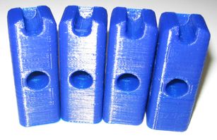
If you have problems printing all four legs at once use the signle stl files and print one leg at a time. Single stl files are also included at the zip file.
1x bearing guide by brnrd

1x y-belt-holder-TrustFm Print the belt holder "y-belt-holder-TrustFm.stl" with the 4 20mm wood screws :
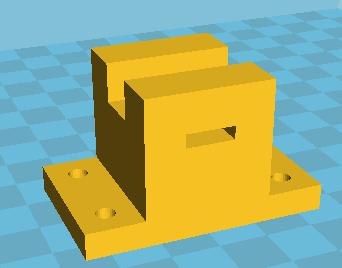
Alternatively you can still use 1x belt holder with two screws located at OLD/y-belt-holder 2 screws.stl

3x bushings

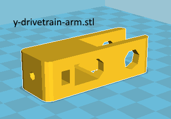
1x y-drivetrain-arm.stl
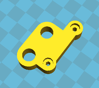
1x y-drivetrain-motor.stl
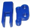
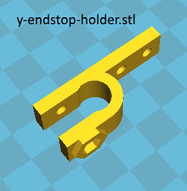
1x y-endstop holder

1x y-endstop spacer
Download all stl files of the y axis here : y-axis-stl
Place your components on a table
Assemble the two M10 threaded rods like the photo below.
Notice that you have to use eight M10 washers and eight M10 nuts for this step.
Pay attention at the order of the washers / nuts.
Snag the lm8uu bearing into the bushing like the photo below :
Now insert the bearing into the M8 linear rod.
Do this procedure into all three bushings.
At this stage avoid using the M3 25mm bolts and nuts. We will place them in a second time.
Now assemble the two linear M8 rods like the photo below :
Insert two lm8uu bearings into the first rod and only one into the second one.
Find your four y axis corners :
Assemble your rods like the photos below :
Place the four external M10 washers and nuts like this :
Screw the M10 nuts loosely by hand.
Assemble the M8 threaded rod with the first part of the drive train.
For this part you need 4x M8 nuts and washers.
Assemble the second M8 rod like the photo below.
For this part you need 2x M8 nuts and washers
Assemble the third and forth M8 threaded rod with the second part of the drive train like the photo below.
For this step you need 8x M8 nuts and washers .
Assemble all the structure like this :
Section 1 - Wooden frame : part 1 - part 2 - part 3
Section 2 - Y Axis : [[ part 1 ]] - part 2 - part 3
Section 3 - X-Z axis : part 1 - part 2
Section 4 - Extruder : part 1 - part 2 - part 3
Section 5 - Electronics : part 1 - part 2 - part 3
Section 6 - Coarse Calibration & Software : part 1 - part 2 - part 3
Section 7 - Fine Calibration & Software : part 1 - part 2 - part 3
Section 8 - Extras : part 1 - part 2 - part 3
Section 9 - Maintenance & Modding : part 1 - part 2