Constructing a 3D Printer [Prusa I3]
SECTION 2 - Y axis - Page 3
Section 1 - Wooden frame : part 1 - part 2 - part 3Section 2 - Y Axis : part 1 - part 2 - [[ part 3 ]]
Section 3 - X-Z axis : part 1 - part 2
Section 4 - Extruder : part 1 - part 2 - part 3
Section 5 - Electronics : part 1 - part 2 - part 3
Section 6 - Coarse Calibration & Software : part 1 - part 2 - part 3
Section 7 - Fine Calibration & Software : part 1 - part 2 - part 3
Section 8 - Extras : part 1 - part 2 - part 3
Section 9 - Maintenance & Modding : part 1 - part 2
In this third part we will place the heatbed.
Cut the two springs at halfs like the photo below
Or just use four 4x 23mm length 9mm diameter springs.
File three M3 30mm bolts and one 40mm bolt like the photos below :
Now place temporarily the heat bed. The assembly can be found down.
For this step you need :
3x M3 30 mm bolts
1x M3 40 mm bolt
1x MK2 heat-bed
4x M5 washers
4x springs
4x M3 nuts
Fix the bed into the wooded tray using : bolt / heatbed / M5 washer / spring / wooden tray / M3 nut sequence.
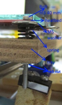
Instead of the M5 washers you can use M3 and M8 washers in cascade for each bolt like the photo below (older option).

The 40mm bolt you have to place it at the front right hole as you see the printer. We will call it "y endstop screw"
Here is the final result :
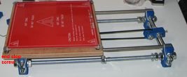
Enlarge the two holes of the mechanical endstop using a 3 mm (M3) drill bit.
Create a new hole for the endstop handle and cut the handle at the red line.
For the new "y-endstop holder.stl" this step is not needed just use the two holes.
Place the "y-endstop spacer" block or if you do not have it use a wooden spacer 2cm tall and drill two M3 holes at 1cm distance each.
Solder the endstop with the endstop cable like the photos below :
Notice the polarity of the cables. Black-front, Red-back.
The yellow wire is not needed [optical endstop] just isolate it.


Use two M3 40mm for the wood block, or two M3 30mm for the plastic spacer in order to fix the endstop with the PLA y-bracket and one M3 25mm to secure the bracket with the M10 rod.
You also need three M3 nuts.
The final result and placement of the y endstop :
Machine using the new y-endstop-holder and the plastic endstop spacer.
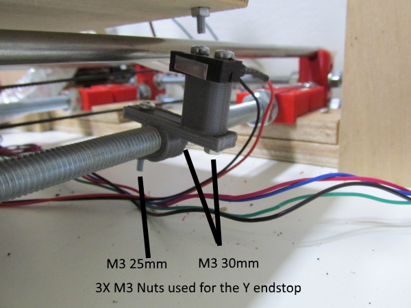
Another machine with the y-endstop flipped for better impact.
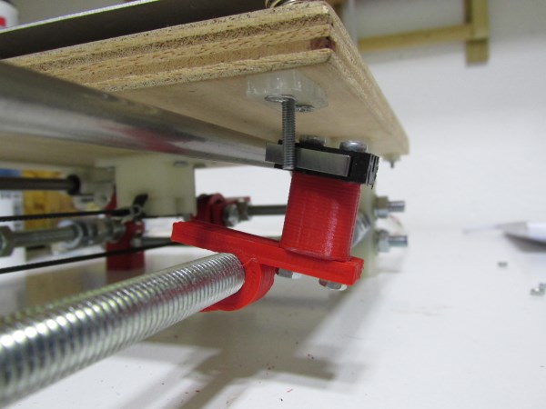
Yet another older machine with a closer look of the endstop using the wooden block:
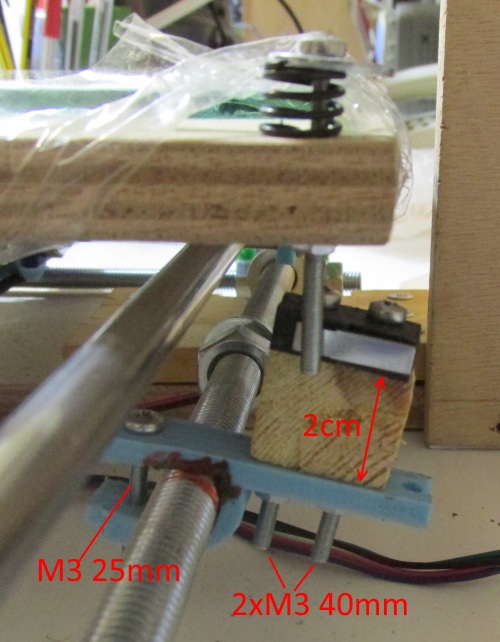
Even older machine :
With a diamond file grind all the 12 sharp edges of the glass :

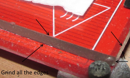
and place it like this :
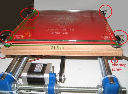
Place four 15 mm binder clips in order to hold the heatbed it the glass


The final result is here :
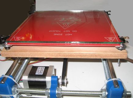
Important notice : The four y axis brackets where not used yet. We need first to make the X-Z plane and then we will fix the y axis with the frame. For now leave the y axis seperate from the frame.
We are done ! The next step is the X Z axis.
Stay tuned !
Section 1 - Wooden frame : part 1 - part 2 - part 3
Section 2 - Y Axis : part 1 - part 2 - [[ part 3 ]]
Section 3 - X-Z axis : part 1 - part 2
Section 4 - Extruder : part 1 - part 2 - part 3
Section 5 - Electronics : part 1 - part 2 - part 3
Section 6 - Coarse Calibration & Software : part 1 - part 2 - part 3
Section 7 - Fine Calibration & Software : part 1 - part 2 - part 3
Section 8 - Extras : part 1 - part 2 - part 3
Section 9 - Maintenance & Modding : part 1 - part 2