Constructing a 3D Printer [Prusa I3]
SECTION 5 - Electronics - Page 2
Section 1 - Wooden frame : part 1 - part 2 - part 3Section 2 - Y Axis : part 1 - part 2 - part 3
Section 3 - X-Z axis : part 1 - part 2
Section 4 - Extruder : part 1 - part 2 - part 3
Section 5 - Electronics : part 1 - [[ part 2 ]] - part 3
Section 6 - Coarse Calibration & Software : part 1 - part 2 - part 3
Section 7 - Fine Calibration & Software : part 1 - part 2 - part 3
Section 8 - Extras : part 1 - part 2 - part 3
Section 9 - Maintenance & Modding : part 1 - part 2
We need to prepare our Ramps 1.4
Solder the diode like the photos below.
Please notice the polarity.
Unbox your four StepStick A4988 drivers.
Solder carefully all the pin legs of the A4988 drivers.
Measure the resistor Rs.
Unfortunately not all the A4988 drivers have the same Rs resistor.
We need to find this value in order to limit our maximum current.
We must not exceed 1.7A for our 42BYGHW811 motors.
We must not exceed 1.5A for our 42BYGHW609 motors.
We must not exceed 1A for our 42BYGHW804 motors.
Try to find out your correct type of stepper motor driver that you use.
For the pololu we have Rs=0.05 Ohm (labeled with "R050")
Ebay blue stepstick. Rs=0.1 (labeled with "R100")
Older reprapworld stepstick Rs=0.2 Ohm (labeled with "R200")
Be aware that these stepsticks have a 1A max output current.
If you have these kind of stepsticks you should use 42BYGHW804 motors (max 1.2A) instead of 42BYGHW811(max 2.5A).
A better and more secure way to find Rs is to measure the two Rs resistors with a precise multimeter into the Ohm range.
I am going to use a UT61E multimeter.
We need a multimeter capable to "detect" two digits after the decimal point.
In order to do this measurement you need to attach the two leads and press the relative button (Δ). Be sure you get relatively 0 ohms. This way you set the relative resistance of the multimeter leads to zero.
If you get 0.01 Ohm for example retry by pressing the relative button (Δ) again.
Below is the measurement of the ebay stepstick Rs=0.1 Ohm
Place the heatsinks to the drivers. Do not ignore this step.
Pay attention to not short-circuit some pins with the heatsink
Make sure that all three jumpers need to be placed under each stepper driver. (red yellow blue in the photo above). We setting 1/16 micro stepping by installing all jumpers under the drivers. Place the four drivers at Ramps.
Notice the polarity.
Place a heatsink to the MOSFET Q3.
Notice that the Q3 is the MOSFET used for the heatbed
The assembly order is :
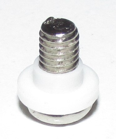
Screw head / Insulation Bushing / Mosfet Hole / Insulation Film / Heatsink TO-220
Please do not ignore the insulation bushing & film.
Take a look at the picture below :
A lot of you keep asking me questions about this step and why is this important.
It is crucial that you place a heatsink at your Q3 mosfet.
Ramps come with different mosfets. Mine usually have the ST P55NF06 mosfets.
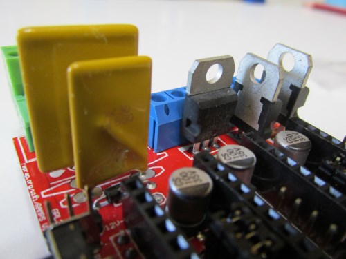
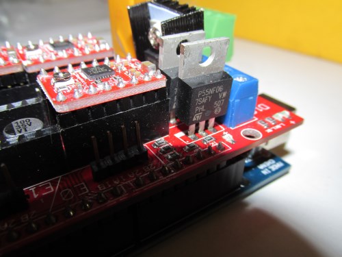
Some of the mosfet options are (from better to worst) :
IRLB3034PBF Rds=1.5/1000 Ohm RJunctionAmbient=62C/W
IRF3703 Rds=2.8/1000 Ohm RJunctionAmbient=62C/W
IRLB8743PBF Rds=3.2/1000 Ohm RJunctionAmbient=62C/W
IRF3708 Rds=12/1000 Ohm RJunctionAmbient=62C/W
ST P55NF06 Rds=15/1000 RJunctionAmbient=62C/W
IRFZ44N Rds=18/1000 Ohm RJunctionAmbient=62C/W
For a heatbed we know that the resistance of the heatbed is 1.2 Ohm.
So V=I*R=> Iheatbed=V/R=12/1.2=10A
So Pheatbed=V*Iheatbed = 12V*10A = 120Watt
Let's take the worst case scenario Pheatbed=120Watt. => I=10A
Pmosfet_P55NF06_loss = I^2 * Rds = 10^2 * 15/1000 = 1.5Watt lost over the mosfet P55NF06
In order to calculate the temperature we use the formula below :
Ttotal = Pmosfet_P55NF06_loss * RJunctionAmbient + TRoom = 1.5*62+25 = 118 Celcius
As you can see the P55NF06 becomes pretty hot so you have to use a heatsink.
Notice that max operating junction temperature for the P55NF06 is 175 Celcius so using a heatsink the mosfet can work at these conditions.
Later we will see for security reasons that we will drop the power by a 200/255=0.784 factor so we can consider that the heatbed is limited at 95Watts instead of 120Watts.
So we reach at most P=V*I=>I=P/V=95/12=8Amps
Pmosfet_P55NF06_loss = I^2 * Rds = 8^2 * 15/1000 = 0.96Watt lost over the mosfet P55NF06
Ttotal = Pmosfet_P55NF06_loss * RJunctionAmbient + TRoom = 0.96*62+25 = 85Celcius.
On the other hand if you use an IRLB3034 mosfet we have :
Pmosfet_IRLB30346_loss = I^2 * Rds = 10^2 * 1.5/1000 = 0.15Watt lost over the mosfet IRLB30346
Ttotal = Pmosfet_IRLB30346_loss * RJunctionAmbient + TRoom = 0.15*62+25 = 34.3 Celcius
This makes the heatsink optional for the IRLB30346 mosfet.
For heatsink i have found over the years three options over ebay :
1) TO-220 Heatsink Heat Sink 20x15x10mm Set
Silicone Rubber Pad 19mm*13mm*0.3mm
M3 TO-220 Nylon Insulation Bushing 6mm outer diameter 3mm inner diameter
M3 6mm long screw
2) TO220 19x15x10mm
3) TO-220 Heatsink 25*15*10mm Aluminum Heat Sink With Needle
I suggest buying the first option that includes everything.
If you got the bigger Heatsink 25*15*10mm you need to cut it down like the photos below to become a 20x15x10mm heatsink
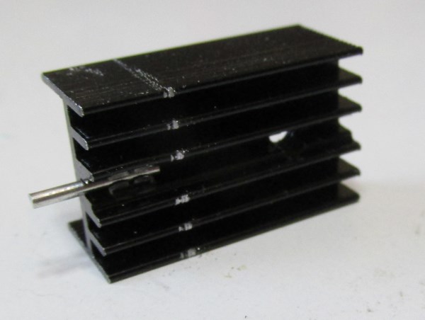
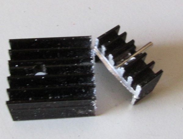
Now you have to grind with a file the back of the heatsink like the picture below. Notice that you don't have to grind all the back of the heatsink . Only the part from the M3 hole and below.
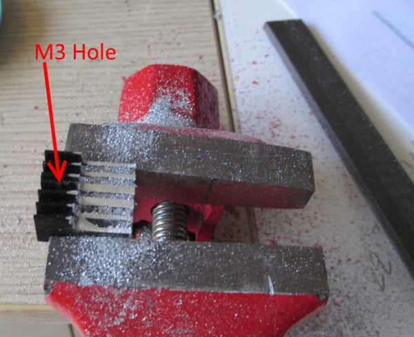
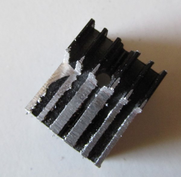
The hole treated set :
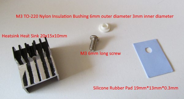
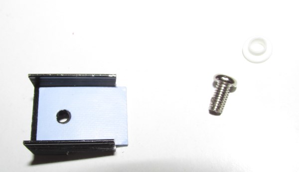
Now place the silicone rubber pad in the heat sink like the picture below :
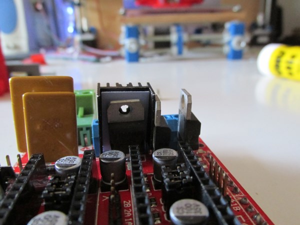
Now place the heatsink behind the mosfet Q3 like the picture below :
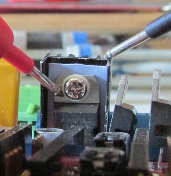
Pick the M3 bolt and place the nylon insulation bushing. This step is important !
Insert the bolt into the heatsink and fix it.
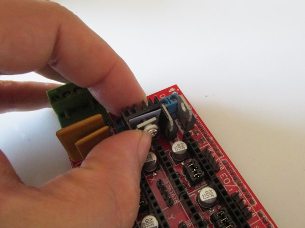
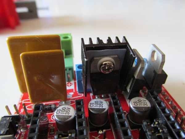
Using a multimeter in continuity mode make sure that the Mosfet chassis is not in contact with the heatsink.
Also make sure that the heatsink does not touch the Mosfet Q2 chassis.
For the hotend resistor the worst case scenario is Photend=40Watt.
Notice that the newer heating elements included at the E3D V6 are rated 25Watts.
Photend=40Watt=V*I=>I=P/V=40/12=3.33A
Pmosfet_P55NF06_loss = I^2 * Rds = 3.33^2 * 15/1000 = 0.16 Watt lost over the mosfet Q1 P55NF06
Ttotal = Pmosfet_P55NF06_loss * RJunctionAmbient + TRoom = 0.16*62+25 = 35 Celcius
As you can see the mosfet Q1 does not need any heatsink.
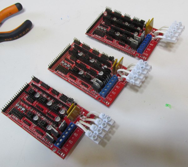
Unfortunately my experience of years show to me that the green four pin ramps jack needs to be replaced because if you try to use your heatbed above the 30 Celcius the ramps jack will melt.
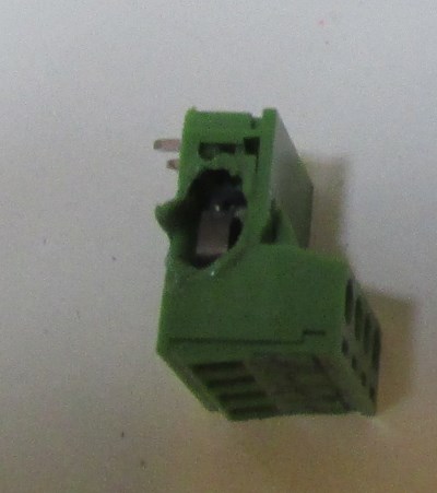
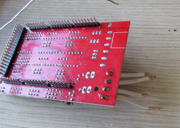
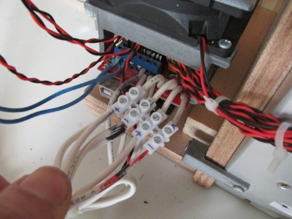
I strongly suggest to replace the green four pin ramps jack with a four screw nylon terminal block wire connector 3mm, using electrical cable 0,75mm^2 like the pictures below :
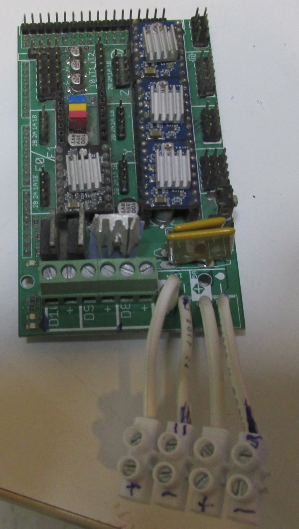
Clip Ramps board over the arduino mega board.
Now we have to do all the cabling.
Find your cables.
x3 for the endstops
x4 for the motors [X,Y,Z,Extruder]
x2 for the thermistors [Extruder,heatbed]
x2 [one parallel pair] for the heatbed 60cm up to 1 meter long
The schematic :

Plugging the cables :
Connect the heatbed with ramps by doing these steps :
Free the heatbed from the tray by unscrewing the bolts.
Parallelize the two pair cables and make one thicker pair 60cm - 1 meter long.
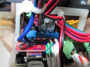
Connect to the D8 (-) slot the negative pair and into the D8 (+) the positive pair like the photo below
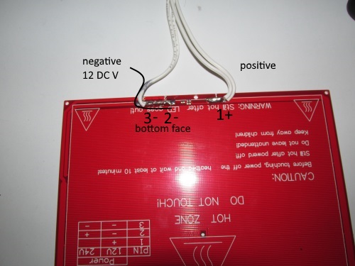
If you have the MK2a 12V heatbed (older version) solder the positive and negative pairs into the pads like the photo below:
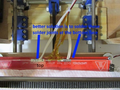
Update : it is way better to make these solder joints at the bottom face of the heat bed and not from the top as shown at the picture.
If you have the MK2b version (dual power new version. best option) then you should solder the wires like the picture below.
Notice that we use the 12V configuration so we have to short pins 2 and 3.
We solder the cables at the bottom face of the plate.
If you have the MK2b black version (single sided PCB board).
You should solder the cable from the top face.
Use a glass in order to prevent the solder going under the glass.
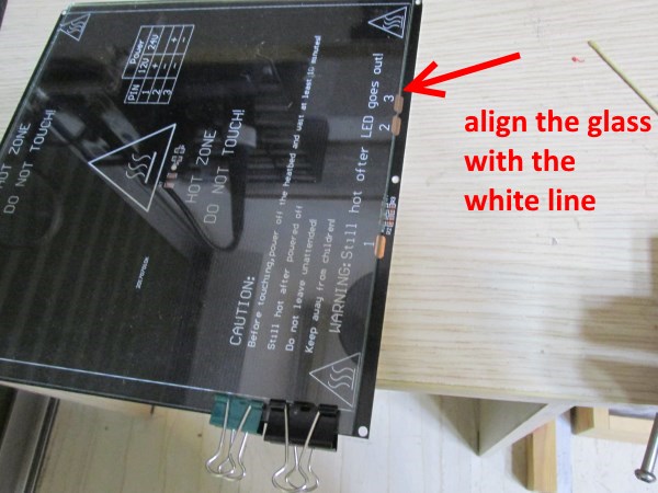
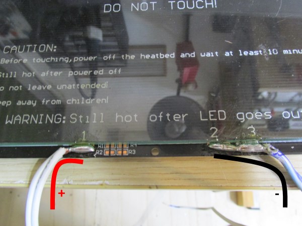
Below you can see the final result. :
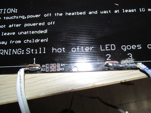
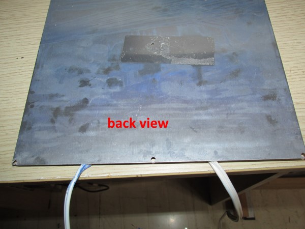
Now it is time to connect the thermistor into the heatbed.
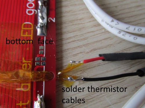
Separate the two legs of the thermistor EPCOS B57560G104F or ATC Semitec 104-GT2 and isolate each leg with kapton tape.
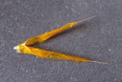
Pass the thermistor thought the hole then bent it and keep it stable using kapton tape.
Make sure that the head of the sensor is at the bottom face of the heatbed.
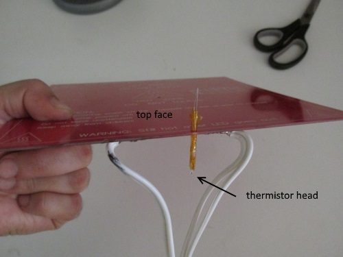
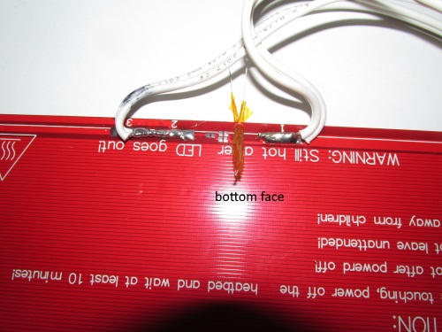
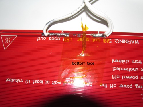
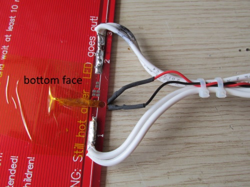
Twist and solder the sensor cables. Do not forget to isolate them using heatshrink tubings.
Use zip ties in order to fix all cables like the pictures below :
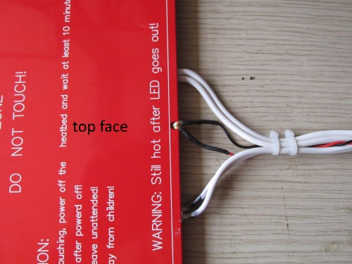
In the "black edition" MK2b the procedure is similar :
Put the thermistor like this :
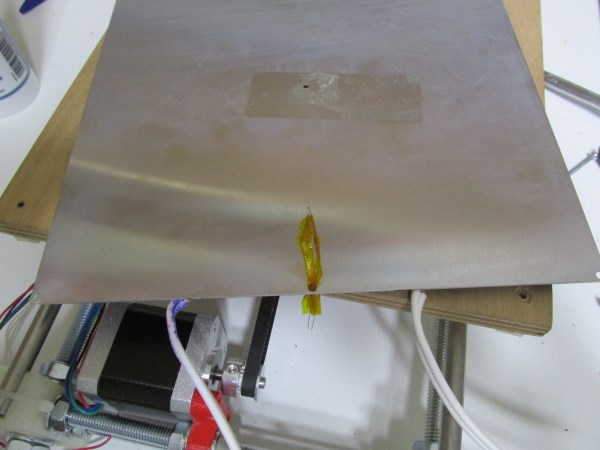
and use kapton tape in order to fix it at the bottom of the plate.
Top view :
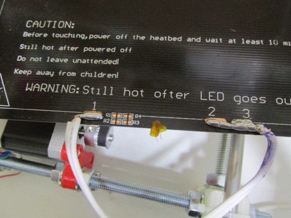
Here is the final result after soldering the thermistor:
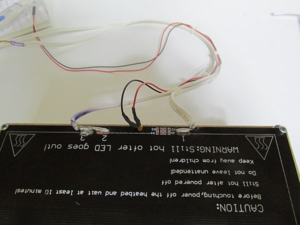
Plug carefully all your wires into ramps like the two photos below :
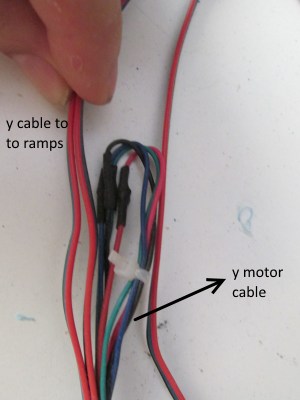
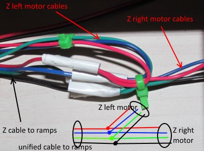
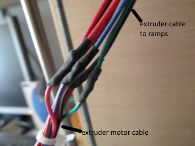
Do not forget to solder the motor cables with the ramps cables. Pay attention soldering the same color cables.
Take a look at the photos below :
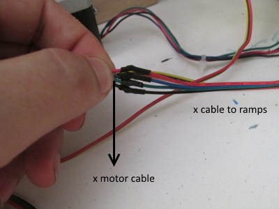
Notice : into the T0 you have to plug the extruder thermistor and into T1 the heatbed thermistor. Thermistors does not have a polarity.
In the next part we will finalize the electronics section.
Section 1 - Wooden frame : part 1 - part 2 - part 3
Section 2 - Y Axis : part 1 - part 2 - part 3
Section 3 - X-Z axis : part 1 - part 2
Section 4 - Extruder : part 1 - part 2 - part 3
Section 5 - Electronics : part 1 - [[ part 2 ]] - part 3
Section 6 - Coarse Calibration & Software : part 1 - part 2 - part 3
Section 7 - Fine Calibration & Software : part 1 - part 2 - part 3
Section 8 - Extras : part 1 - part 2 - part 3
Section 9 - Maintenance & Modding : part 1 - part 2