Constructing a 3D Printer [Prusa I3]
SECTION 2 - Y axis - Page 2
Section 1 - Wooden frame : part 1 - part 2 - part 3Section 2 - Y Axis : part 1 - [[ part 2 ]] - part 3
Section 3 - X-Z axis : part 1 - part 2
Section 4 - Extruder : part 1 - part 2 - part 3
Section 5 - Electronics : part 1 - part 2 - part 3
Section 6 - Coarse Calibration & Software : part 1 - part 2 - part 3
Section 7 - Fine Calibration & Software : part 1 - part 2 - part 3
Section 8 - Extras : part 1 - part 2 - part 3
Section 9 - Maintenance & Modding : part 1 - part 2
Make sure that the M10 rods have distance 170 mm with the caliper.
Make sure that there are parallel.
Fix the nuts by hand for now.
Make sure that the drive train belt will pass in the middle of the frame (85mm each side).
Front part :
Back part :
Insert the bearing guide into the 608zz bearing
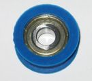
Use the M8 30mm bolt with a M8 nut in order to lock axis of the bearing.
Make sure that the bearing is spinning freely if not grind the drive train arm.
The newer "y-drivetrain-arm.stl" file should not have this issue.
Now place a M3 nut into the drive train like this :
Add a M3 screw 30 mm :
Put eight external M8 nuts and washers in order to lock the hole structure.
With two M3 10mm bolts fix the motor into the drive train.
Also lock the GT2 20 teeth pulley with the two M3X5 grub screws that came with.
Do not forget to snag the bushings into the linear bearings (lm8uu) like the picture below.
At this point it is not necessary to place the three M3 25mm bolts.
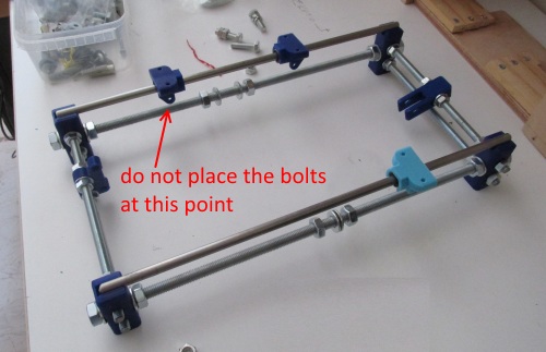
The assembly so far :
It is time to place the tray.
Print the Tray-LibreCAD.dxf pattern into two A4 pages and join them with scotch tape.
Place the pattern into your wooden tray.
Drill four M3 holes (3mm drill bit) at the edges of the tray.
Screw with four M3 20mm wood screws at the center of the tray the belt holder.
The correct position of the belt holder is indicated at the Tray-LibreCAD.dxf file
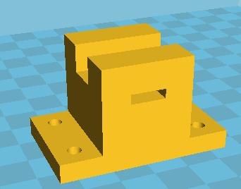
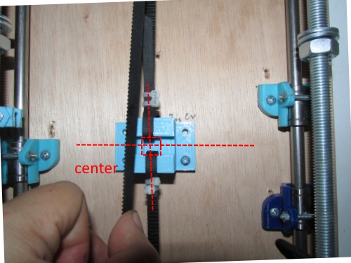
Older - two screws - belt holder version (obsolete)
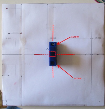
Now pass the GT2 belt without snapping any part of the belt holder.
Cut the excess of the 1 meter belt.
Use zip ties in order to lock the GT2 belt.

Align the tray. This is the most important part.
As i said my original plastics kit did not had the three y bushings so i hand made metal ones.
Do not screw the any wood screws yet.
Measure with the digital calliper the indicated distances [photo below].
Make sure that your linear M8 rods have a fix distance of 170 mm in all of their length.
Both red distances must be the same [less than a mm of difference].
Mine using my handmade bushings were around 35mm
The same must be true for the green distances.
Below you can see the same procedure done on another machine that had the y bushing brackets.
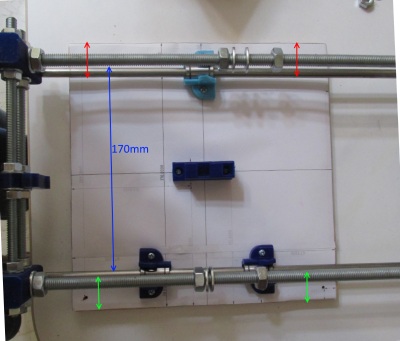
Sign the correct positions of the three bushings. Should be the same of your printed pattern.
Screw the bushings carefully using two wood screws for each bushing (six wood screws)
Make sure that the tray is moving freely without putting any force
If it is not moving freely do not put any force.
Check the alignment of your bushings (remeasure the red/green distances).
Check the distance of your M8 linear rods (170mm).
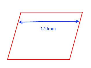
Make sure your parallelepiped is rectangular.
Notice that you can have a "undesired" parallelepiped with a distance of 170mm like the image below [top view] :
Once you have done the tray alignment and the tray can be moved straight and without any extra force then you should gently lock all the nuts of your construction using a wrench.
This action should be done slowly with extra care and it is time consuming.
Tight the bolts two at a time and always check to see if the tray can move in a straight line without any extra force.
Make also sure that the belt is always in the middle of the metal frame and forms a straight line, if not, move slightly the plastic drive train.
Once done with the tray alignment place the zip ties at the four y axis corners :
New machine using y-axis-corner22-ziptie.stl (with zip tie hole)
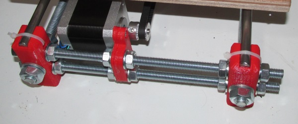
Older machine using y-axis-corner-long.stl (no zip tie hole)
Using the M3 drive train bolt you can stretch the GT2 belt.
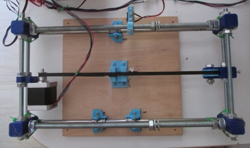
The final assembly so far [top and bottom]
Another machine using the alternative belt holder and the plastic bushings:
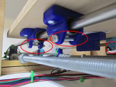
Once you have fixed the tray you can use three M3 25mm bolts and three M3 nuts in order to lock the bushings with the plastic y-brackets
In the 3rd part of y axis assembly we will see how to place correctly our heatbed.
Section 1 - Wooden frame : part 1 - part 2 - part 3
Section 2 - Y Axis : part 1 - [[ part 2 ]] - part 3
Section 3 - X-Z axis : part 1 - part 2
Section 4 - Extruder : part 1 - part 2 - part 3
Section 5 - Electronics : part 1 - part 2 - part 3
Section 6 - Coarse Calibration & Software : part 1 - part 2 - part 3
Section 7 - Fine Calibration & Software : part 1 - part 2 - part 3
Section 8 - Extras : part 1 - part 2 - part 3
Section 9 - Maintenance & Modding : part 1 - part 2