Constructing a 3D Printer [Prusa I3]
SECTION 4 - Extruder - Page 1
Section 1 - Wooden frame : part 1 - part 2 - part 3Section 2 - Y Axis : part 1 - part 2 - part 3
Section 3 - X-Z axis : part 1 - part 2
Section 4 - Extruder : [[ part 1 ]] - part 2 - part 3
Section 5 - Electronics : part 1 - part 2 - part 3
Section 6 - Coarse Calibration & Software : part 1 - part 2 - part 3
Section 7 - Fine Calibration & Software : part 1 - part 2 - part 3
Section 8 - Extras : part 1 - part 2 - part 3
Section 9 - Maintenance & Modding : part 1 - part 2
It is time to assemble our extruder.
In this article we will be limited to the Greg's wade v3 direct extruder.
This extruder has four main parts :
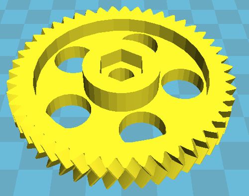
1) Big gear (biggearmod_fixed.stl):
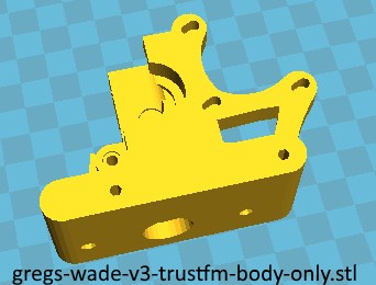
2) Greg's wade v3 direct extruder body (gregs-wade-v3-trustfm-body-only.stl):
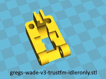
3) Greg's wade idler
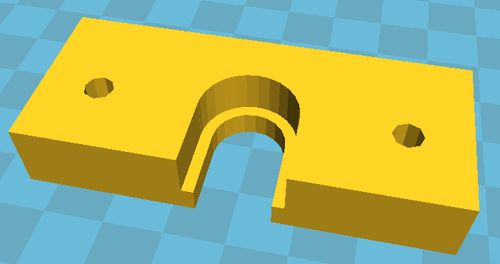
4) Groove mount (groovemount.stl) :
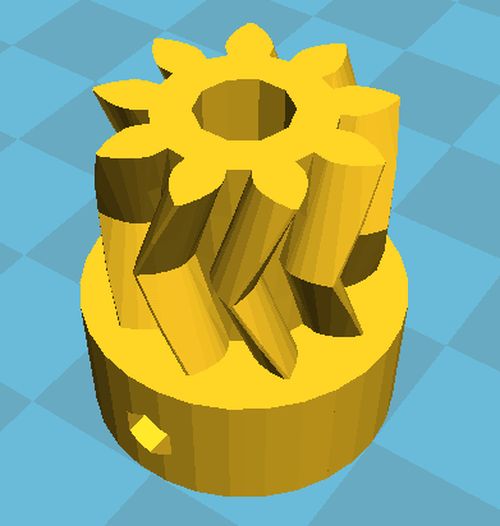
5) Small gear (smallgearmod_fixed.stl):
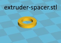
6) Extruder spacer (extruder-spacer.stl)
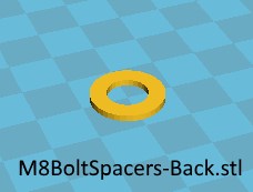
7) M8 Hobbed Bolt spacer back (M8BoltSpacers-Back.stl)
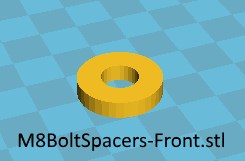
7) M8 Hobbed Bolt spacer front (M8BoltSpacers-Front.stl)
All the parts can be downloaded from here : Greg's wade v3 direct extruder
First of all grab your Greg's wade v3 direct extruder and snap the part shown in the photo.
Now grind the central hole with a M8 drill bit.
For the six smaller holes use a M3 drill bit to do the same job.
The finished job :
Now pick the extruder idler, grind the lips and then install the 608zz bearing using a 20mm M8 smooth rod
Now place two M3 nuts like the photo below. You also will need a 30 mm M3 bolt later.
Take the big gear and with a M8 drill bit and open the central hole.
Using the M5 drill bit this time do the same for the small gear
Place a M3 nut at the bottom of the small gear.
Take your extruder motor [1x extruder motor 42BYGHW609] and screw the small gear onto the motor.
I have used the 42BYGHW609 stepper motor since it is lighter than the 42BYGHW811 (2.5A) and uses less current (1.7A)
You can also use the 42BYGHW804 with current rating 1.2A or the 42BYGHW811 with current rating 2.5A but these are heavier than the 42BYGHW609.
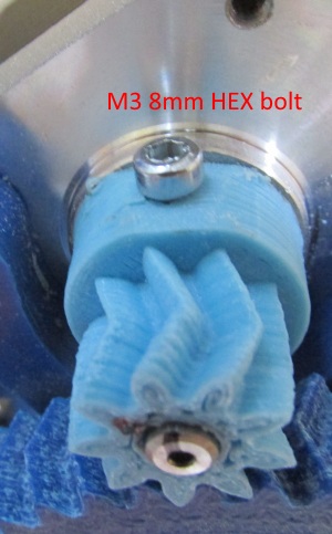
Use a 8mm M3 bolt
I have found that it is better to use a 8mm M3 hex bolt in order to fix the gear with the motor since it offers a better grip.
Also notice that i have light - sanded around the bolt hole in order to increase the depth of the bolt.
This small pulley is fragile you should print some spares with 40%-100% infill once your machine is ready.
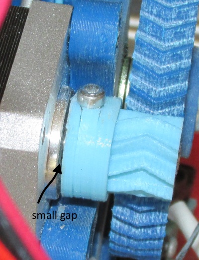
Notice that once mounted the pulley you should have a small gap between motor and the bottom of the pulley like the photo below :
Place the two 608zz bearings in the Greg's wade body like this :
Place the extruder idler using a M3 30mm bolt :
This step is optional but it is recommended.
If you want to be able to print flexible filaments and generally make your extruder more reliable you need 32.5mm PTFE tube 4mm OD / 2mm ID.
Pick a M4 drill bit and enlarge the central hole of the extruder like the pictures below.
Now cut the top edge of the tube like the picture below.
Insert the tube like the pictures below
With a pen sign where you have to cut the PTFE tube. In our case the length sould be around 32.5mm.
Now remove the PTFE tube and cut it.
Measuring the PTFE tube
Now re-insert the PTFE tube like the pictures below:
On another machine :
Now it is time to install our hobbed bolt into our extruder.
If you have a "hobbed bolt ver 1.1" like the photo below then proceed reading else go to the "normal / ebay hobbed bolt" section.
Try the hobbed bolt
Now using two wrenches screw the "header" locknut extremely slowly.
You must be carefull to align the teeth of the hobbed bolt with the hole.
Once you are sure with the alignment place the hobbed bolt to the big gear
Place the two M8 washers or even better the "M8 Hobbed Bolt spacer front":
Mount the motor on the Greg's wade body using three M3 10 mm bolts :
Here is the correct assembly :
Front view :
At the back we must place a washer (or M8 Spacer back), one full nut and one half nut :
If you don't have a half nut you can make one from a normal M8 nut by grinding one of it's faces.
You do not have to be exact.
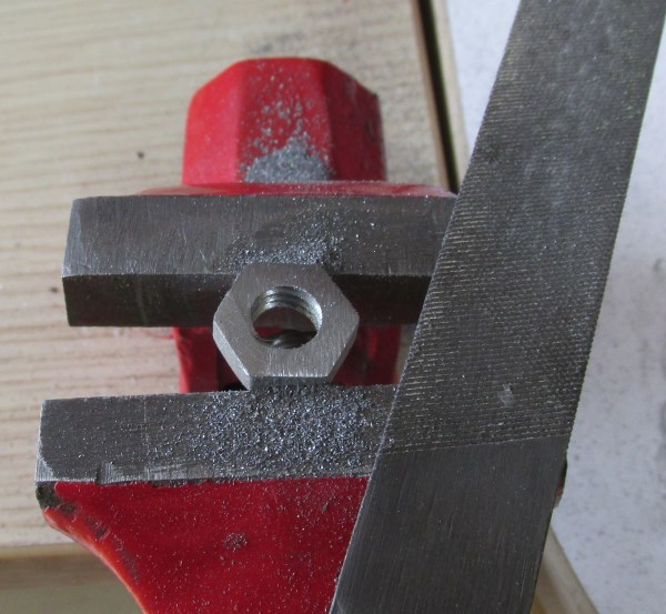
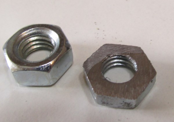
Use the ungrinded face of the nut against the full nut like the picture below.
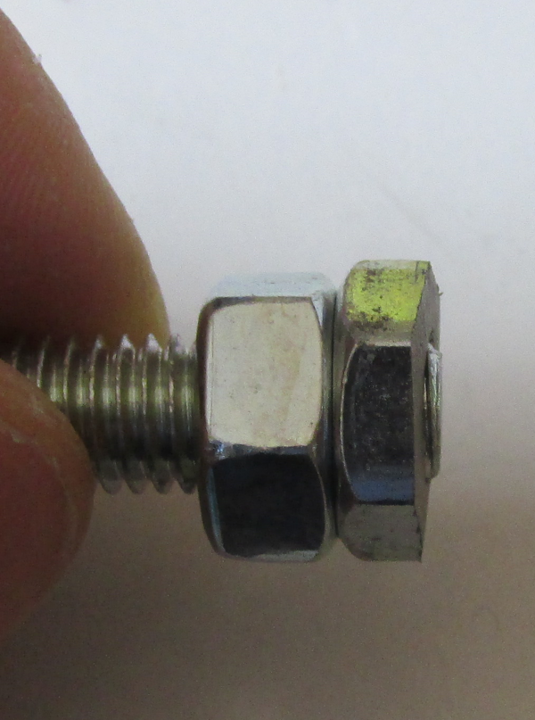
Final result :
Normal / ebay hobbed bolt case :
If you have a classic hobbed bolt like the picture below :
Assemble your extruder like the picture below, using 1 washer , then two washers and two M8 nuts.
Pay attention at the alignment of the hole with the hobbed bolt.
If you have alignment problems you might need to grind the single M8 washer.
Some more self explanatory photos are below :
Notice that in this gear the bottom M8 nut was loose inside the big gear so i added black electrical tape around the nut in order to fix better the nut into the gear.
In the next part we will mount our hot end into our extruder.
There the "Extruder spacer" part is needed.
Section 1 - Wooden frame : part 1 - part 2 - part 3
Section 2 - Y Axis : part 1 - part 2 - part 3
Section 3 - X-Z axis : part 1 - part 2
Section 4 - Extruder : [[ part 1 ]] - part 2 - part 3
Section 5 - Electronics : part 1 - part 2 - part 3
Section 6 - Coarse Calibration & Software : part 1 - part 2 - part 3
Section 7 - Fine Calibration & Software : part 1 - part 2 - part 3
Section 8 - Extras : part 1 - part 2 - part 3
Section 9 - Maintenance & Modding : part 1 - part 2