Constructing a 3D Printer [Prusa I3]
SECTION 6 - Coarse Calibration & Software - Page 3
Section 1 - Wooden frame : part 1 - part 2 - part 3Section 2 - Y Axis : part 1 - part 2 - part 3
Section 3 - X-Z axis : part 1 - part 2
Section 4 - Extruder : part 1 - part 2 - part 3
Section 5 - Electronics : part 1 - part 2 - part 3
Section 6 - Coarse Calibration & Software : part 1 - part 2 - [[ part 3 ]]
Section 7 - Fine Calibration & Software : part 1 - part 2 - part 3
Section 8 - Extras : part 1 - part 2 - part 3
Section 9 - Maintenance & Modding : part 1 - part 2
At this point you have set up all the endstops correctly and you should have leveled the heatbed successfully.
Now you can move in all directions (x/y/z) more freely.
Let's calibrate the x/y/z axis steps.
The method is the same.
Home all 3 axes. Move the X by 100mm using Host-Repetier.
Now measure the distance using a digital caliper.

If you are way off the 100mm take a look at the X-axis and tighten or loose the X screw of the tension belt shown in the picture below.
There must be some error with your 3D printer.
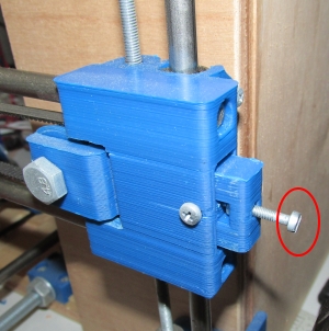
If you have done everything right you should get exactly 100mm as measured distance.
As you remember the steps from our configuration firmware are :
#define DEFAULT_AXIS_STEPS_PER_UNIT {80.00,80.00,4000.00,650.00}
Now instead of 100mm you get 101mm even if you twicked the belt use the formula below :
new_firmware_steps = (repetier_distance_mm/measured_distance_mm) * current_firmware_steps
So in our case :
firmware_new_steps = (100/101) * 80 = 79.20
Now disconnect Repetier-Host go to Arduino IDE and load "Marlin.ino"
Go to "Configuration.h" and change like this :
#define DEFAULT_AXIS_STEPS_PER_UNIT {79.20,80.00,4000.00,650.00}
Now save it and press the upload button in order to update the new firmware.
Reconnect Repetier-Host and home all axes again.
Now move again 100mm the x axis and rechech the distance.
Repeat the process if needed.
For example now you are getting 99.96mm
firmware_new_steps = (100/99.96) * 79.20 = 79.23
So disconnect Repetier-Host, modify the firmware, save it and then re-upload it.
At this point i have to stress the fact that in all of my machines that i have made the X/Y/Z steps are 95% the times spot on.
So before changing the firmware steps specially if the numbers are way off take a look at your machine.
For example make sure that RAMPS uses 1/16 microstep mode (all three jumpers are used under each driver)
Now it is time to calibrate the y axis steps.
Home all 3 axes. Move the y by 100mm using Host-Repetier.
Now measure the distance. If you are way off the 100mm take a look at the y-axis and tighten or loose the y screw of the tension belt shown in the picture below.
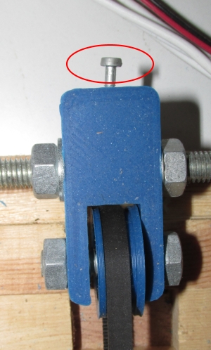
Again the correct steps for this calibration is 80.00 or as close as you can get.
Take your time tweaking the y-belt
If you have follwed our tutorial the z-steps should be 4000.00
Again if you have small variations use the formula:
new_firmware_steps = (repetier_distance_mm/measured_distance_mm) * current_firmware_steps
like before.
Now it is time to tune our two thermistors.
The one located at the extruder and the other on the heatbed.
For this project we have used EPCOS B57560G104F thermistors.
So at our "Configuration.h" we have used
TEMP_SENSOR_0 1 and TEMP_SENSOR_BED 1
since "1" is 100k thermistor - best choice for EPCOS 100k (4.7k pullup)
Notice that E3D v6 nozzle now uses : 100K Semitec 104GT2 NTC thermistor
so you have to use TEMP_SENSOR_0 5
since "5" is 100K thermistor - ATC Semitec 104GT-2 (Used in ParCan & J-Head) (4.7k pullup)
#define TEMP_SENSOR_0 1 //was -1 0 ignore temp
#define TEMP_SENSOR_BED 1 //was 0
There are two supported methods in order to control thermistors.
The bang bang mode which simply opens and closes the thermistor when need it and the PID method.
The PID method produces more accurate results (the temperature oscilate a lot less) but needs more CPU.
On the other hand bang bang mode needs less CPU.
We are going to use the bang bang mode for the heatbed thermistor and the PID mode for the extruder.
We will start calibrating the heatbed thermistor since it is easier.
As you can see from the "Configuration.h" file the PIDTEMPBED is commented (has // at the beggining) meaning that we are using bang bang mode for the bed and not PID
//#define PIDTEMPBED
Remember our power supply is 12V and 20A.
So the maximum power is Psupply=V*I=240W
Now remember that we have 4 motors at 1,2A / 12V so the motors consume Pmotors=4*1.2*12=57.6W
The resistor of the extruder is rated Pextruder=40W (Infact i measured the resistor end was 3.6 Ohm . V=I*R=>I=3.33A Pextruder=12*3.33=40W)
The motor of the extruder is Pextruder_motor=1A*12V=12W
The heatbed has a resistance of 1 Ohm => V=I*R => I=12A and Pheatbed=12A*12V=144W
So the Ptotal=Pmotors+Pextruder+Pextruder_motor+Pheatbed=253W which is bigger that the Psupply=240W !
In real life using my Prusa at max i got a Ptotal=210W this is due to the fact that Pextruder is limited by the PID.
Anyway it is not recommended to stress that much your power supply.
So i suggest to lower the Pheatbed from 144W to 110W by changing MAX_BED_POWER from 255 to 200.
This change is already done by default by me at the given firmware in order to protect your power supply.
Feel free to lower even more that number (180 for example).
Calculate the power you want by doing : Pheatbed=144*MAX_BED_POWER/255 Watts
#define MAX_BED_POWER 200 // limits duty cycle to bed; 255=full current
Using my wattmeter my Prusa I3 with MAX_BED_POWER 200 consumes max 175Watts. (Normally 50W when it does not heat the bed which is the 85% of the time)
Using PLA you need to add glue in the glass in order to stick your print with the bed.
You need a glue stick that is based on PVA or PVP.
I have tested and recommend 3M Scotch glue stick(green), Elmer's Washable Repositionable Glue Sticks and Logo stik.
The 3M Scotch glue stick(green) creates a small film over the glass and can be used multiple times without any problem.
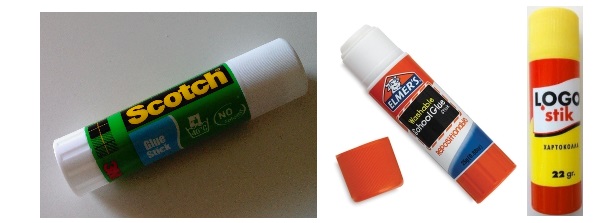
Avoid using hair spray lacquer or any "natural" glue sticks.
UHU used to be a good option (left) but the newer natural (right) version it is not any more recommended.
They decided to make the UHU stick more "natural" making this product unusable.
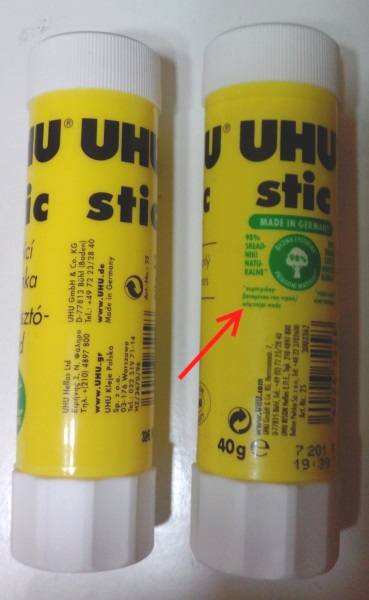
In conclusion do not use hair spray lacquer, UHU, Pritt or any cheap dollar store / Chinese glue sticks.
I do not use ABS so i can not recommend anything.
For gluing down ABS i have heard about a solution of acetone with ABS but as i said i have not tested anything about this.
This tutorial is focused on PLA.
Since we are going to use glue stick and PLA the temperature we need for the bed is at most 40ºC.
Anything above 60ºC is not recommended.
I personally use 40ºC since that temperature "activates" the glue the winter and the summer.
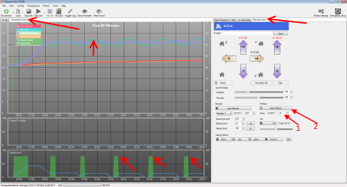
Now run Repetier-Host and press the connect button. For security reasons bring the nozzle to a distance of 10cm from the heatbed.
Now set 40ºC and hit the "Heat Printbed" button.
Take a look at the "Temperature curve" tab.
Notice that you have 80% peaks into the "Output Bed chart" located at the bottom of the screen
Also notice the oscillation that bang bang mode has (blue line)
Watch the curve for 10 minutes and see if everything works ok.
If you have problems check your thermistor connection with the RAMPS.
Once you are happy about the results feel free to stop heating the bed.
Now let's move on to the extruder thermistror.
Again make sure you move the nozzle to a distance of 10cm from the heatbed (z axis). As we said in this case we are going to use the PID mcontrol method.
As we can see from the "Configuration.h" the PIDTEMP is uncommented (enabled ):
#define PIDTEMP So we need to define the Kp Ki and Kd values
The given firmware has these values which work well :
#define DEFAULT_Kp 17.09 //12.53 //22.2
#define DEFAULT_Ki 1.01 //0.61 //1.08
#define DEFAULT_Kd 72.10 //63.85 //114
If you have heating stability issues or errors at new marlin 1.14 use the default values :
#define DEFAULT_Kp 22.2
#define DEFAULT_Ki 1.08
#define DEFAULT_Kd 114
Let's tune more these values. We are going to set a target temperature of 200ºC which is a really good starting point for printing PLA. So hit the "Toggle Log" button from the top of Repetier-Host and then hit the "Manual" tab.
Also hit the "Temperature curve" in order to see what is going on.
Now write the command : M303 S200 and hit "Send".

Now wait for 3/4 minutes . Repetier host from the Log file will give you the Kp, Ki and Kd values that you need to insert into your firmware.
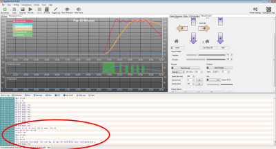
Fell free to repeat the test and take the averange values for Kp, Ki and Kd.
Write down your Kp, Ki and Kd values. Now disconnect Repetier-Host, load "Marlin.ino" into Arduino GUI go to "Configuration.h" and change DEFAULT_Kp, DEFAULT_Ki and DEFAULT_Kd values.
Save the file and press the upload button.
Now we need to test the extruder thermistror with our new values.
So we go to Repetier-Host and re-connect to the printer.
Press the "Manual" tab and.
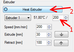
Set 200ºC and and press the "Heat Extruder" button.
See how stable is the temperature line.
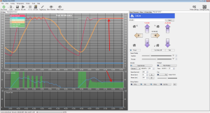
Temperature line should be stable, if not, you have to redo the PID test or make sure which thermistor do you use in reality and in the firmware.
Notice : do not go over 220ºC for PLA. Play around 190-205ºC.
Now we only need to calibrate the extruder (Count e-steps / Coarse calibration).
Again make sure you move the nozzle to a distance of 10cm from the heatbed.
For this calibration is better to use a light colored filament.
Now open the Greg's wade port and insert your PLA 1.75mm filament.
The filament should go around 9cm deep
Screw the two horizontal bolts of the extruder port.
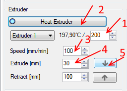
Press heat the extruder and wait till you reach 200ºC.
Now set a speed of 100mm/min and set extrude[mm] to 30mm.
Now press the extrude down button.
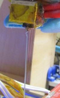
You should not get errors and make your first extrusion.
If you have problems check your extruder assembly and recheck if you inserted the filament correctly.
If you hear noise (clogging) then try lowering the speed but again most of the times is a hardware problem.
Recheck your machine starting from the extruder assembly.
If simply you did not extruded nothing try extruding another 30mm of fillament.
Below you can see the extruded filament :
Once your extruder is extruding correctly measure with your digital caliper 100.00 mm of filament from the top of the extruder port like the photo below. With a pen mark the 100.00mm distance.
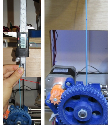
Now extrude 50mm of filament using Repetier-Host at a 100mm/min speed.
Re-measure from the spot the distance to the top of the port like the photo below :
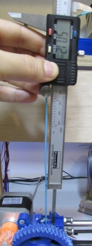
In our case we have 50.12mm remaining filament.
So we effectively extruded 100-50.12=49.88mm of filament instead of 50mm (under-extrusion)
Again using the formula :
new_firmware_steps = (repetier_distance_mm/measured_distance_mm) * current_firmware_steps
we have in our case :
new_firmware_steps = (50/49.88) * 650 = 651.56
To be honest i am currently using a 950 estep value.
So i need to change my e-steps :
new_firmware_steps = (50/49.88) * 950 = 952 but i prefer to under-extrude a little bit.
As you can see 650 is really a small number for Greg's Wade extruder but is always better to start under-extruding and slowly increase the e-steps.
It is way better to under-extrude than over-extrude since you are risking breaking the small 9-teeth pulley of your extruder.
This happened to me twice.
Infact one of your first prints should be this small pulley ;)
Now disconnect Repetier-Host go to Arduino IDE and load "Marlin.ino"
Go to "Configuration.h" and change like this :
#define DEFAULT_AXIS_STEPS_PER_UNIT {80.00,80.00,4000.00,YOUR_NEW_ESTEP_VALUE}
Now save it and press the upload button in order to update the new firmware.
You can go ahead and re-connect Repeter-Host.
Doing this calibartion again is always a good tip.
Move the hot nozzle at zero height and redo a bed levelling.
Make sure that the small papper still passes below the nozzle. Try different X,Y points as always.
We have finished our coarse calibration of the machine.
Now we are ready to start printing !
In the next section we will talk about the fine calibration and software tools that we need in order to start printing.
Section 1 - Wooden frame : part 1 - part 2 - part 3
Section 2 - Y Axis : part 1 - part 2 - part 3
Section 3 - X-Z axis : part 1 - part 2
Section 4 - Extruder : part 1 - part 2 - part 3
Section 5 - Electronics : part 1 - part 2 - part 3
Section 6 - Coarse Calibration & Software : part 1 - part 2 - [[ part 3 ]]
Section 7 - Fine Calibration & Software : part 1 - part 2 - part 3
Section 8 - Extras : part 1 - part 2 - part 3
Section 9 - Maintenance & Modding : part 1 - part 2