Constructing a 3D Printer [Prusa I3]
SECTION 4 - Extruder - Page 2
Section 1 - Wooden frame : part 1 - part 2 - part 3Section 2 - Y Axis : part 1 - part 2 - part 3
Section 3 - X-Z axis : part 1 - part 2
Section 4 - Extruder : part 1 - [[ part 2 ]] - part 3
Section 5 - Electronics : part 1 - part 2 - part 3
Section 6 - Coarse Calibration & Software : part 1 - part 2 - part 3
Section 7 - Fine Calibration & Software : part 1 - part 2 - part 3
Section 8 - Extras : part 1 - part 2 - part 3
Section 9 - Maintenance & Modding : part 1 - part 2
We will also present in parallel the E3D V6 1.75 mm full metal hot end.
The official documentation by the manifacturer can be downloaded from here :
E3D V5 1.75 mm full metal hot end
E3D V6 1.75 mm full metal hot end
E3D V5/V6 instructions :
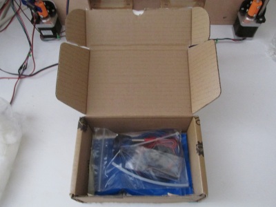
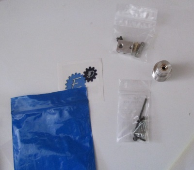
Unbox the E3D v5 package
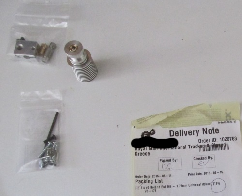
The E3D v6 comes in a similar box. The barrel is smaller. The heater block has a slice in order to add the heating element.
No kapton tape is used, instead they give you a blue fiberglass tubing for the thermistor.
Also the thermistor has changed they give you a ATC Semitec 104-GT2 instead of the EPCOS B57560G104F.
Also the V6 uses PTFE tube and has a blue heating element (25W) instead of the red one (40W).
We grind a little bit the Greg's wade hole.
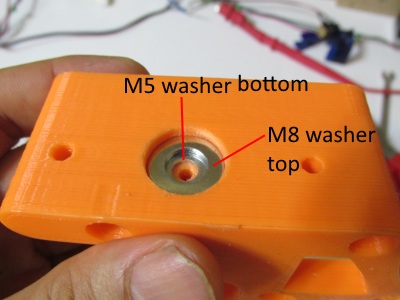
In the E3Dv5 case we are going to add a M8 washer into the Greg's wade hole.
In the case of E3D v6 we are going to add two washers a M5 and a M8 like the photo below.
Now we test the E3D v5/v6 with our Greg's wade body.
Place the groove mount like the photos below.
If the barrel won't fit grind again a little bit the hole.
Once you are sure that the barrel fits into the Greg's wade body you can start assembling the hot end.
For the E3D V5 : Screw the short end of the stainless steel heatbreak into the heater block until the start of the constriction is flush with the top of the heater-block.
Screw the nozzle into the heater block until it butts up against the heat-break inside the block, just finger tight is fine for now.
The hexagonal flat portion should not touch the block, there should be a tiny gap between the flat area and the block.
Notice again that the nozzle should tighten up against the end of the break inside the block to form a seal. It should not tighten up against the block.
Strip the wire. Strip 20mm of the soft outer insulation and then 10mm of the inner two cores.
Spread the legs of the thermistor [EPCOS B57560G104F] slightly, just enough that they aren't touching, take the two bootlace ferrules and slide onto the thermistor legs with the funnelled mouth facing away from the glass bead. Take a look below :
Now twist the cables like the photo below and cover each joint with a bootlace ferrule.
Using pliers crush the ferrule tube tightly around the wire joints to form a strong joint that is also heat-proof.
You should have something like this :
Cover each individual leg with kapton tape like the photo below :
Make sure that the two legs are well isolated with kapton tape.
Now again using kapton tape hold both legs into a single stripe :
Place the thermistor as shown below.
Use kapton tape to block it.
Use the tiny M3 grub screw and the supplied small hex-wrench to secure the resistor (heating element 40W - 12V) in place.
Do not over tighten the grub screw, it just needs to secure the resistor in place.
Notice that the E3D V5 comes with a 12V - 40W heating element.
Since P=V*I => I=P/V=40W/12V=3.33A .
And from ohms law we have V=I*R => R=V/I=12V/3.33A=3.6 Ohms.
So our heating elements should have a resistance of 3.6 Ohms
Below we can see the measurement made for the heating element of the E3D v5 using a multimeter (Ohms position)
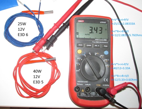
Pretty similar procedure is for the E3D V6 :
Screw the short end of the stainless steel heatbreak into the heater block until the start of the constriction is flush with the top of the heater-block.
Screw the nozzle into the heater block until it butts up against the heat-break inside the block.
Remember to only hand screw the assembly at this point.
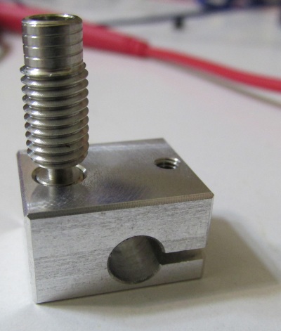
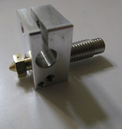
Now cut the fiberglass tube into two 35mm pieces like the photo below :
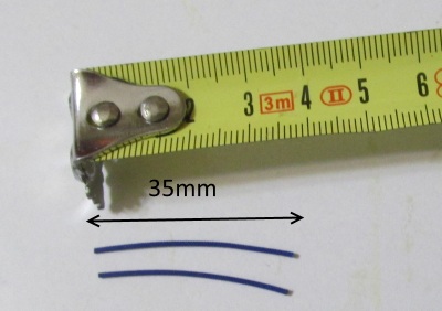
Do not cut the fiberglass tube in half.
Spread the legs of the ATC Semitec 104-GT2 and pass the two fiberglass tubes.
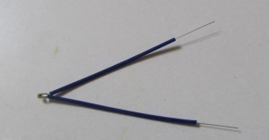
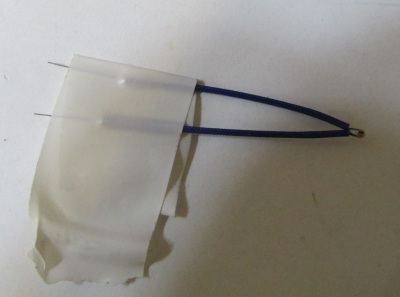
Use electrical tape to fix temporarely the fiberglass tube with the legs of the thermistor like the photo below.
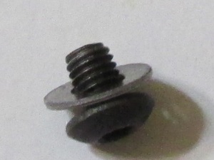
Now using the small M3 4mm hex screw and a washer fix the thermistor at the block.
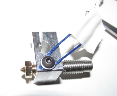
Notice that the blue fiberglass must cover the legs of the thermistor all the way down to the sensor.
Once secured the sensor you can remove the eletrical tape.
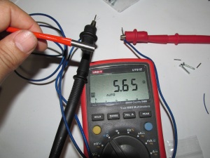
Using a multimeter we can see that the given heating element for the E3D v6 has 5.76 Ohms of resistance.
Since P=V*I => I=P/V=25W/12V=2.08333A .
And from ohms law we have V=I*R => R=V/I=12V/2.08333A=5.76 Ohms.
Now place the heater cartridge into the heating block using the M3 10mm hex screw
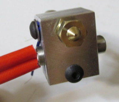
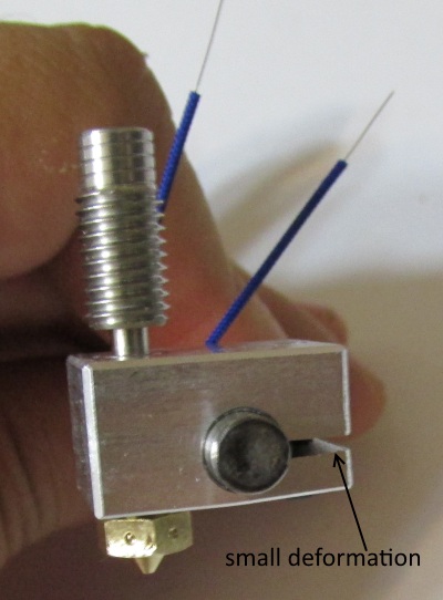
Do not overtight the M3 hex screw . The heating block should be slightly deformed by the pressure of the screw.
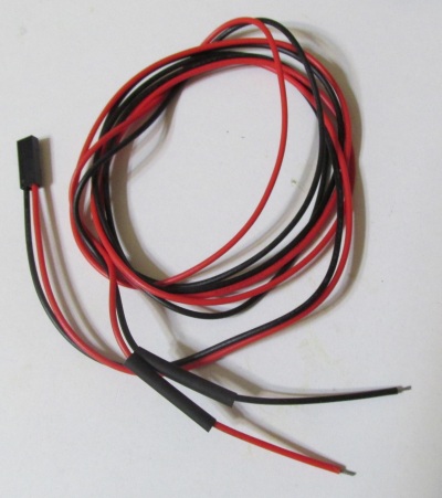
Now cut in half the given heatshrink tube and pass it through the red / black cable
Pass the ferrule tubes at the fiberglass tubing
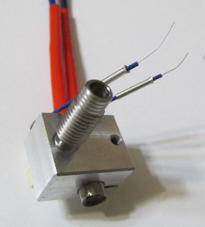
Now connect the wires by twisting them.
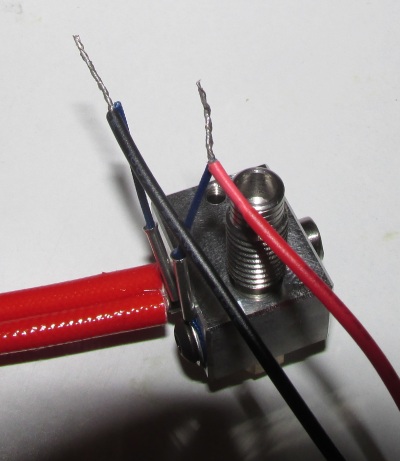
Now move over the joints the ferrule tubes and crush them using pliers :
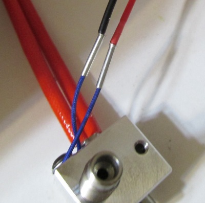
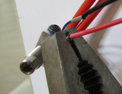
Move over the heatshrink tubes and using a lighter heat shrink them over the joints
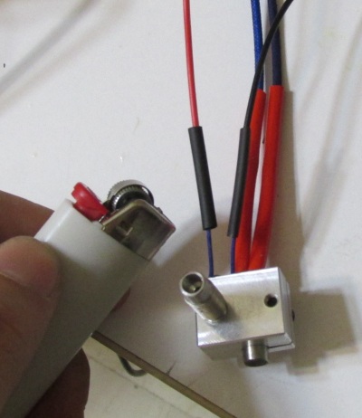
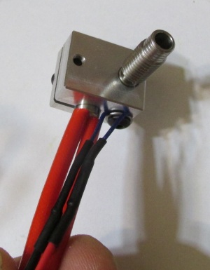
Now hand screw the barrel :
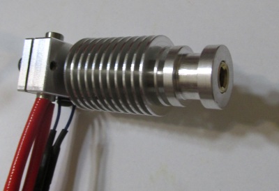
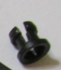
Insert the PTFE stop at the top of the barrel
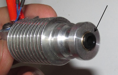
Cut around 37mm of the PTFE tube and insert it into the barrel :
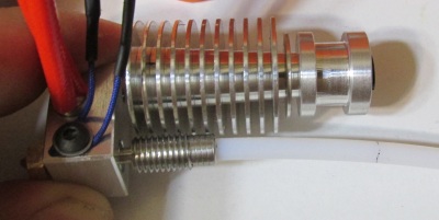
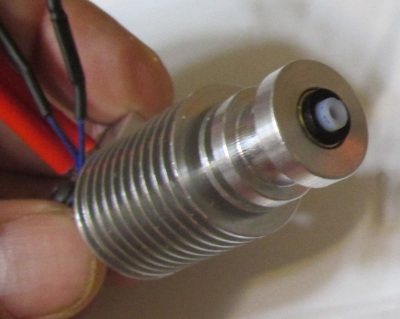
The PTFE tube should exceed by a couple of mm from the top of the barrel.
Now we have mounted our heater cartridge and thermistor into our E3D nozzle. In the next part we will finalize our extruder.
Section 1 - Wooden frame : part 1 - part 2 - part 3
Section 2 - Y Axis : part 1 - part 2 - part 3
Section 3 - X-Z axis : part 1 - part 2
Section 4 - Extruder : part 1 - [[ part 2 ]] - part 3
Section 5 - Electronics : part 1 - part 2 - part 3
Section 6 - Coarse Calibration & Software : part 1 - part 2 - part 3
Section 7 - Fine Calibration & Software : part 1 - part 2 - part 3
Section 8 - Extras : part 1 - part 2 - part 3
Section 9 - Maintenance & Modding : part 1 - part 2