Constructing a 3D Printer [Prusa I3]
SECTION 5 - Electronics - Page 3
Section 1 - Wooden frame : part 1 - part 2 - part 3Section 2 - Y Axis : part 1 - part 2 - part 3
Section 3 - X-Z axis : part 1 - part 2
Section 4 - Extruder : part 1 - part 2 - part 3
Section 5 - Electronics : part 1 - part 2 - [[ part 3 ]]
Section 6 - Coarse Calibration & Software : part 1 - part 2 - part 3
Section 7 - Fine Calibration & Software : part 1 - part 2 - part 3
Section 8 - Extras : part 1 - part 2 - part 3
Section 9 - Maintenance & Modding : part 1 - part 2
Now we have to limit our A4988 drivers using the formula :
Imax = Vref/(8*Rs)
We need to set the X,Y,Z drivers at Imax = 1.2A since we have 42BYGHW811 motors
Notice since the Z motors are in parallel I_z_max=Imax/2 => I_z_max=0.6A
So we have to set :
For a pololu A4988 Rs=0.05 ohm => Vref=0.48V
For a StepStick A4988 Rs=0.1 ohm => Vref=0.95V [this was my case]
For a reprapworld A4988 Rs=0.2 ohm => Vref=1.60V [this kind of stepstick allows max 1A]
For the extruder driver we have to limit it at Imax=1A since i have used a 42BYGHW609 motor
So we have to set :
For a pololu A4988 Rs=0.05 ohm => Vref=0.40V
For a StepStick A4988 Rs=0.1 ohm => Vref=0.80V
For a reprapworld A4988 Rs=0.2 ohm => Vref=1.60V [this was my case]
Calculate Vref using a multimeter at DC volts range.
Turn on the power supply and measure Vref like the pictures below.
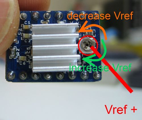
The Vref+ is located at the trimpot of each driver.
Vref- is the ground.
Once measured the Vref switch off the power supply. Turn 15 degrees the trimpot (clockwise increses the Vref) using a small screwdriver.
Remove the screwdriver and then switch on the power supply.
Remeasure Vref again.
Do not try to change Vref with the power on.
Do this procedure for all four drivers individually.

You are almost done !
Using two M3 wood screws 10 mm long, screw the arduino board into the bottom of the wooden frame like the picture below :

Block the power supply with the frame using perforated metal tape.
Top view :

Back view :

Now do some cable managment.
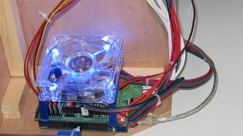
You must also place a 80 mm fan into ramps.
First way - Place by side :
Alternative way - Place over the top :

The printed part shown above (printed twice) can be downloaded here.
It is thing:138370 on thingiverse.
Notice that even if it needed a 60 mm fan i mounted a 80mm fan. It is better to use a 80 mm fan on ramps.
Connect the forth 12V wire with the two 80 mm fans [Ramps fan and power supply fan] and with the small 30mm extruder fan
Notice that the fans have red (+) and black (-) cable.
Connect them with the correct polarity.
Hotglue the 12V screw terminal.

Final result :
By doing this procedure you have set up all your electronic parts.
Your stepper motors should be connected with ramps.
Also both fans (ramps & power supply) should work when the power is on.
By this time we have finished all the construcion of our prusa I3 engine.
The only thing to do is to fix the X-Z frame with the Y axis and start calibrating our machine.
In the next section we will see how we can calibrate our machine and what software we need in order to start printing !
Section 1 - Wooden frame : part 1 - part 2 - part 3
Section 2 - Y Axis : part 1 - part 2 - part 3
Section 3 - X-Z axis : part 1 - part 2
Section 4 - Extruder : part 1 - part 2 - part 3
Section 5 - Electronics : part 1 - part 2 - [[ part 3 ]]
Section 6 - Coarse Calibration & Software : part 1 - part 2 - part 3
Section 7 - Fine Calibration & Software : part 1 - part 2 - part 3
Section 8 - Extras : part 1 - part 2 - part 3
Section 9 - Maintenance & Modding : part 1 - part 2