Constructing a 3D Printer [Prusa I3]
SECTION 6 - Coarse Calibration & Software - Page 2
Section 1 - Wooden frame : part 1 - part 2 - part 3Section 2 - Y Axis : part 1 - part 2 - part 3
Section 3 - X-Z axis : part 1 - part 2
Section 4 - Extruder : part 1 - part 2 - part 3
Section 5 - Electronics : part 1 - part 2 - part 3
Section 6 - Coarse Calibration & Software : part 1 - [[ part 2 ]] - part 3
Section 7 - Fine Calibration & Software : part 1 - part 2 - part 3
Section 8 - Extras : part 1 - part 2 - part 3
Section 9 - Maintenance & Modding : part 1 - part 2
Before starting our fine tuning calibration we need to pilot the machine using Repetier-Host for Windows.
Notice that the new versions of Repetier-Host do not have that great manual support.
I recommend using the "Repetier-Host Windows 0.95F" version from the older versions section.
If you have problems finding this old version you can download it from here (yandex disk). Download and install Repetier-Host at your PC.
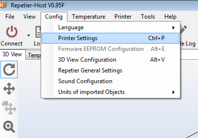
Now press "Config" > "Printer settings"
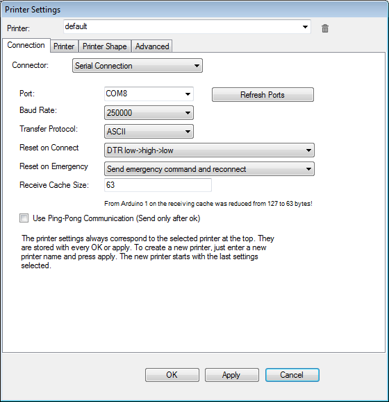
Press the "Connection" tab and do as the photo below :
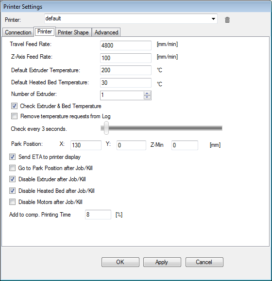
Press the "Printer" tab and do as the photo below :
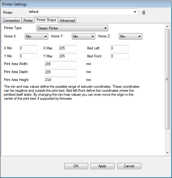
Press the "Printer Shape" tab and do as the photo below :
If for any reason do not like repetier host or you just have problems you can try pronterface instead.
Set it up like this :
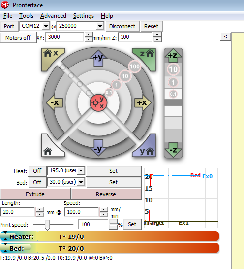
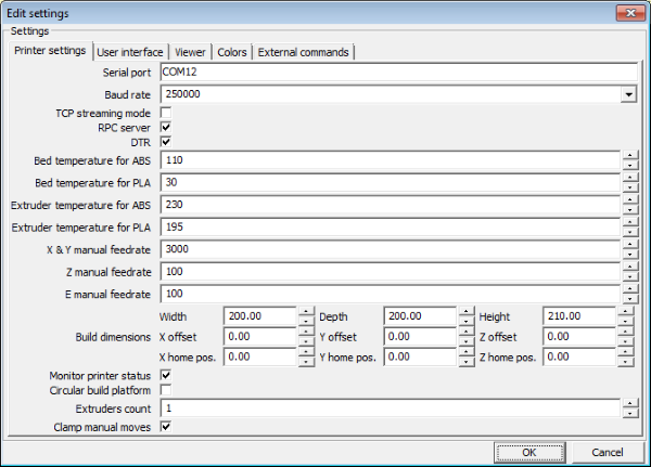
Now hit "Settings" > "Options" and do like the pictures below :
"Printer settings" tab :
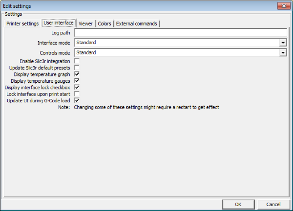
"User interface" tab :
Pronterface unfortunatelly does not detect the current position of the machine so we have to add a custom button with the gcode command M114.
We hit the "+" button from the bottom of the main screen.
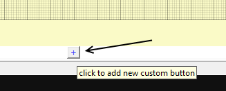
Now we fill the "Custom button" window like this :
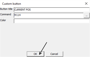
By hitting the "CURRENT POS" button we get the actual position of our printer.
Click on "Port" in order to detect all available COM ports.
Select the COM port of your printer from the list.
Select 250000 as speed and hit the "Connect" button
In this tutorial we will use repetier host in order to pilot our printer but you can use pronterface similarly.
A special note for Linux users. A lot of people can not use the 250000 baudrate as speed and keep changing this setting.
This is wrong since by changing the baudrate you are introducing transmission error. More info at wormfood.
Notice that specially the 115200 speed introduces an -3.5% transmission error which is the main cause of stalled/frozen long prints.
By using the 250000 bautrate you get 0% error at 16Mhz AVR chips. So instead lowering speeds do like so under Linux :
Via terminal (konsole) :
dmesg | grep tty
This command will list all the recognized USB devices. Try to find where is attached the arduino USB converter.
Usually is attached at "/dev/ttyUSB0"
Now send this command via terminal (konsole) :
sudo chmod a+rw /dev/ttyUSB0
Set baudrate at 250000 by downloading mysetbaud.py
Unzip "mysetbaud.py" at /home/YOURNAME/YOURPATH/
Now from the konsole do :
cd /home/YOURNAME/YOURPATH/
./mysetbaud.py <>/dev/ttyUSB0 250000
Now you are ready to use the printer at 250000 baudrate speed.
Now power up the printer :
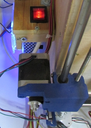
Run repetier host.
Press the "Connect" button. Once successfully connected the "Connect" button should become "Disconnect"

Now you can pilot your printer manually for the first time by pressing the "Manual Control" tab.
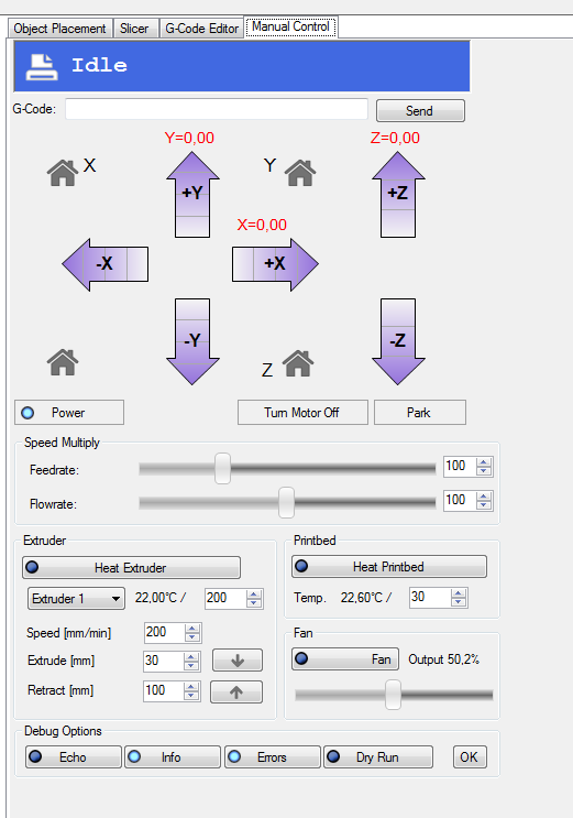
The first thing to do is to move up the z axis by 1mm

You should have no errors by doing this. If you get problems make sure that you have oiled the M5 threaded rods and that the X axis if perfectly horizontal.
If you hear strange noises as last bet try lowering the acceleration of the z axis from 4 to 3.4 for example.
To do this press the "Disconnect" button at Repetier-Host go to Arduino IDE and load "Marlin.ino"
Hit the "Configuration.h" tab and do this change :
from : #define DEFAULT_MAX_ACCELERATION {1000,1000,4,3000}
to : #define DEFAULT_MAX_ACCELERATION {1000,1000,3.4,3000}
Now reconnect with Repetier-Host.
Notice : the given default accelerations should not have problem if you have followed our tutorial.
We have tested in more than one machine these values with success out of the box.
So before trying modifing the firmware watch for mechanical errors first.
If everything is ok move another time up the z axis for 10mm this time and while the machine moves up the z axis press by hand the z-axis endstop switch. The z axis should stop.
Do the same procedure with X and Y axis. Move at most 1mm the machine when you first try. Test all three endstops by hand.
Now test the home button for the X axis.

Do the same with the Y axis.
Before homing the Z axis make sure that the endstop work and it is placed at least 5cm above the glass of the tray.
Now home carefully the Z axis the nozzle should be away at least 2 cm from the glass. This is ok for now.
Now it is time to do the bed levelling of the machine.
Loose almost fully all four screws of your headbed in order to find the fully decompressed max level.


Now move down the nozzle by moving the z endstop gradually and by using the Z-Home button from Repetier-Host. You have to place the nozzle between the fully decompressed / fully compressed levels.
This is pretty easy to do since you have 5mm gap.
Once the nozzle is between this zone secure tightly the Z-endstop. You have successfuly and permanetly fixed the Z-endstop.

Once the nozzle is between the fully decompressed / fully compressed levels now you can unscrew slightly all 4 screws in order to decrease the noozle / glass gap to 2 mm.
If the gap is too small tight all four screws.
The final result should look like this :

Try homing Z axis again. Make sure you have a gap of 2mm at least.
Now it is pretty easy to fix the X and Y endstops.
Let's start fixing the X endstop. Try homing the X axis.
Fix the x-endstop when the nozzle reached the white line of the heatbed like the photo below.
Note that you can also be off the white line a bit (closer to the glass edge) like the photo below.
Once you are reaching the white line secure tightly the X-endstop.
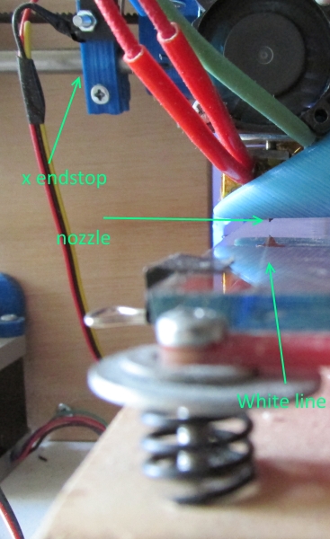
Now move the nozzle 10mm in X-axis direction and home the Y.
By homing the y axis you should arrive at the edge of the glass and not off the glass.
Position the y endstop trying to reach the edge of the glass (or a bit inner) like the photo below.
Once you are covering the glass secure tightly the Y-endstop.
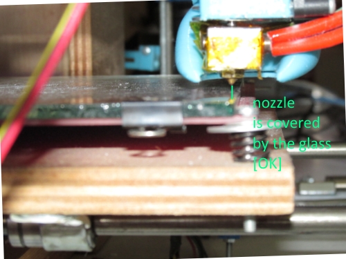
At this point you should have fixed X,Y,Z endstops correctly.
Now we have to level the bed with the nozzle.
To do so divide virtually the headbed in four regions BackLeft/BackRight/FrontLeft/FrontRight like the photo below :
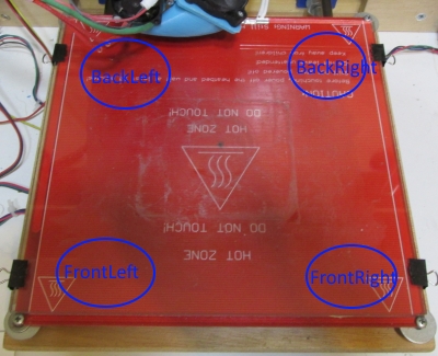
Go using manual control at Repetier-Host to the FL region.
Unscrew the FL bolt until a A4 papper can exactly pass between nozzle and glass.
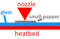
Now slowly move the x axis 10 mm at a time and check if the gap increases or decreases (points : 1,2,3,4,5,6).
Do not move more than 10 mm at a time. Please take your time adjusting only the FR/FL screws.
If increases the gap unscrew the FR bolt else screw more the FR bolt.
Now move back to the FL region (decrease x gradualy). (points : 7,8,9,10,11,12)
Once you are happy with the front regions go from the point 12 to the point 13 moving the y axis again at most 10mm at a time.
If the gap increases unscrew the BL screw else screw more the BL bolt.
Screw/Unscrew the BR screw only if the BR/BL level is really not horizontal.
Do all the path (12,13,...23). Once you are happy with the gap at the points (12..23) go to the FL region again.
Recheck the triangle (FL/FR/BL 1-23 points). Do not bother too much with the BR for now.
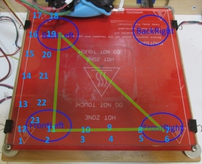
Now move the nozzle into the FR region .
Do the same procedure for the triangle (FR/FL/BR 30-53 points)
In this triangle try to adjust only FR/FL/BR avoiding modifying BL
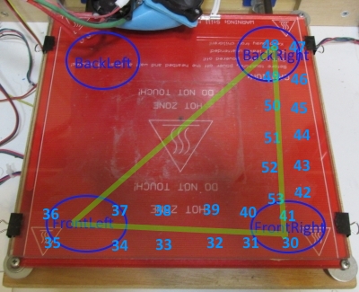
By finishing these two triangulars your heatbed should be leveled.
For more fine tuning do the remaining two triangulars.
So move the nozzle into the BR region.
Do the same procedure for the triangle (BR/BL/FR 60-82 points)
In this triangle try to adjust only BR/BL/FR avoiding modifying FL
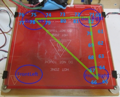
At last move the nozzle into the BL region .
Do the same procedure for the triangle (BL/BR/FL 83-103 points)
In this triangle try to adjust only BR/BL/FR avoiding modifying FR
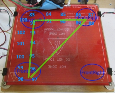
This procedure works because a plane is always defined by 3 points not by 4.
The common mistake is to calibrate the heatbed doing rectagulars (all vertices) and not triangulars.
In the next page we will fine-tune x,y,x and we are going to calibrate thermistors and extruder.
Section 1 - Wooden frame : part 1 - part 2 - part 3
Section 2 - Y Axis : part 1 - part 2 - part 3
Section 3 - X-Z axis : part 1 - part 2
Section 4 - Extruder : part 1 - part 2 - part 3
Section 5 - Electronics : part 1 - part 2 - part 3
Section 6 - Coarse Calibration & Software : part 1 - [[ part 2 ]] - part 3
Section 7 - Fine Calibration & Software : part 1 - part 2 - part 3
Section 8 - Extras : part 1 - part 2 - part 3
Section 9 - Maintenance & Modding : part 1 - part 2