Constructing a 3D Printer [Prusa I3]
SECTION 7 - Fine Calibration & Software - Page 2
Section 1 - Wooden frame : part 1 - part 2 - part 3Section 2 - Y Axis : part 1 - part 2 - part 3
Section 3 - X-Z axis : part 1 - part 2
Section 4 - Extruder : part 1 - part 2 - part 3
Section 5 - Electronics : part 1 - part 2 - part 3
Section 6 - Coarse Calibration & Software : part 1 - part 2 - part 3
Section 7 - Fine Calibration & Software : part 1 - [[ part 2 ]] - part 3
Section 8 - Extras : part 1 - part 2 - part 3
Section 9 - Maintenance & Modding : part 1 - part 2
After Slc3r settings we are ready to do some print tests in order to fine tune our machine.
First of all download the testing procedure models.
Make sure your machine has 0.2mm layer height for the first and for all layers.
Layer width is set at 0.4 mm.
Extract all models from the zip file.
The models are numbered as 01,02,03... this is the order you should print them.
Measure your filament like the photo below (again) and make sure you set the value at Slic3r.
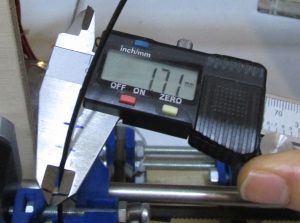
---Final E-step Calibration---
We will start finetuning the e-steps (extruder steps).
Load "01-Thin-Wall-04mm.stl" at Slic3r using the "plater" tab and then hitting the "add" button.
For this object set "Infill density" at 0%
Once you load the stl file at Slic3r from the plater tab press "Export G-code".
Now close Slic3r and run Repetier-Host
Load your generated G-code at Repetier-Host by hitting the "Load" button.
Before start printing add some stick glue to the glass.
Print the object by hitting "Run Job".
Repetier Host should :
1) Heat the bed at 30 degrees
2) Heat the extruder at 200 degrees
3) Home all axis
4) Start printing
Congratulations !
This is your first print. It should be printed within 10min.
Shut down the printer once printed.
Remove the glass from the heatbed and place it into a table.
Then using a knife carefully remove the object from the glass
Place again the glass into heatbed.
Now let cool down the model for at least 30min. This is important since we have to make an exact measurment.
Measure the thickness of the four walls.
Try to measure the smallest number of layers possible from top as the slightest vertical misalignment of your layers will increase the measured value.
Ideally a single layer would be best but very difficult with regular calipers. Take a look at the photo below :
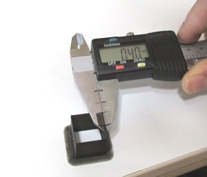
Throw out the largest value, and average the other three values [measured width = (width_wall_1 + width_wall_2 + width_wall_3)/3].
Now using the formula :
new e_steps = (firmware e_steps * slic3r layer width)/(measured width)
You can find your new e_steps.
For my case i had to do :
measured width = (0.44+0.43+0.43)/3 = 0.43333
new e_steps = (950*0.4)/0.43333 = 877
Currently i am using 878.00 as e-step value
Now disconnect Repetier-Host go to Arduino IDE and load "Marlin.ino".
Go to "Configuration.h" and change like this :
#define DEFAULT_AXIS_STEPS_PER_UNIT {80.00, 80.00, 4000.00, YOUR NEW ESTEPS}
Now save it and press the upload button in order to update the new firmware.
Reprint this object and feel free to re-change the estep value untill you get 0.4mm walls.
Feel free to do the "01-Thin-Wall-05mm.stl" using a 0.5mm layer width.
You should get 0.5mm walls.
Take your time with this calibration since it is the most important.
Now print the "01-Cube-Full-Infill-10x10mm.stl" and the "01-Cube-Full-Infill-20x20mm.stl" both of them slice them with 100% infill this time.
With this print you can do two measurements in order to find your e_steps by weight and by eye.
If you have a digital scale you can weight them.
The density of PLA plastic is 1.25 grams per cubic centimeter (1.25 g/cm^3).
So for the :
"01-Cube-Full-Infill-10x10mm.stl" it's weight should be around 1.25gr and
"01-Cube-Full-Infill-20x20mm.stl" around 9.75gr
Try to always extrude a little less (underextrude) than overextruding.
new e_steps for 10x10mm= (firmware e_steps * 1.25)/(measured weight)
new e_steps for 20x20mm= (firmware e_steps * 9.75)/(measured weight)
Now you can update your firmware.
Another way is to compare by eye your prints like the photo below by increasing the estep value by small amounts.
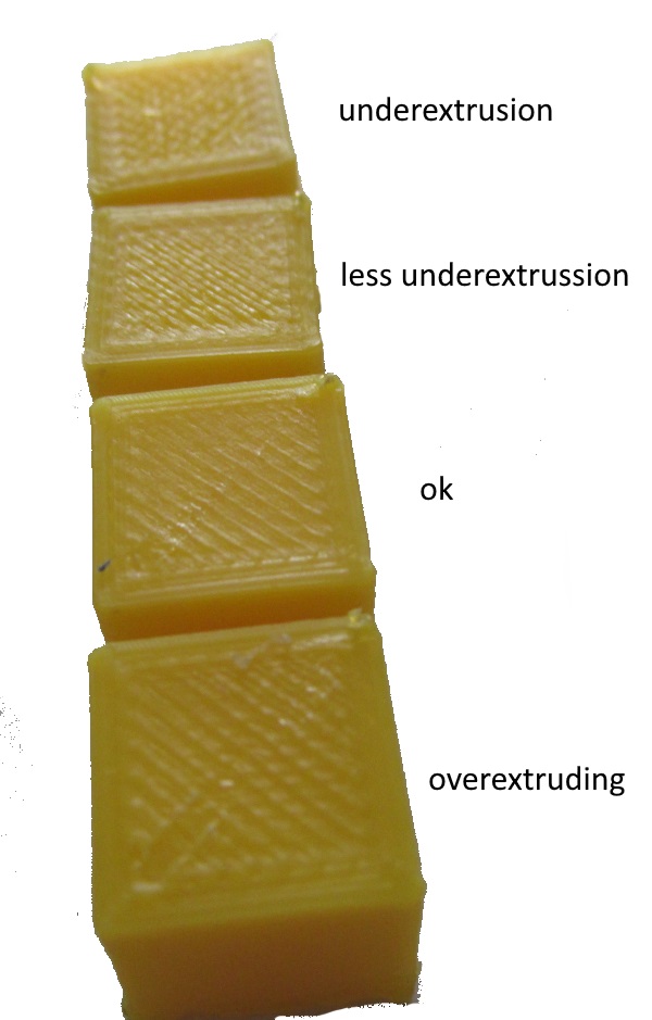
Notice: Same hobbed bolts have way different e-steps. Pay attention to find the correct e-step number for your machine.
---Final heatbed Calibration---
The next step is to check the calibration of the heat bed.
In the coarse section we have roughly calibrated the heat bed.
Now it is time to do some fine tuning.
Clean the glass and add glue.
If you already have glue and it is un-even drop some water (3-4 drops at most) at the center of heat bed and using a small paintbrush make a uniform layer of glue.
Add some new glue over this layer.
Heat the nozzle at 200 degrees Celsius and home the Z axis.
Focus at the four corners of the heat bed. like :
X:20, Y:20
X:20, Y:180
X:180, Y:20
X:180, Y:180
Make sure that at these four points
at Z:0 the A4 paper does not pass between nozzle and glass
instead at Z:0.1mm the A4 paper passes with a small grip between glass / nozzle
(recommended setting)
By doing this procedure is almost certain that you need to raise higher slightly the heat-bed.
If you have adhesions problems even when adding glue you can try at the same four points that
at Z:0.1mm the A4 paper does not pass between nozzle and glass
instead at Z:0.2mm the A4 paper passes with a small grip between glass / nozzle
Now you should generate the G-code for "02-Bed-Calibration-Grid-150x150x1mm.stl" using :
0.4mm layer width
skirt loops 0
brim width 0.8mm (two perimeters 0.4*2=0.8mm)
Infill 20%
Normal speed settings shown in the page before
Once generated the G-code load the file at Repetier-Host and hit the "Run Job"
The print time will be around 50 min.
If you have done the procedure above you should not have problems at first try.
If you have adhesion problems hit the "Kill job" in order to abort the job.
The job should fail while prints the brim 150x150mm border.
In the photo below you can see a good adhesion and a bad adhesion at the same time.
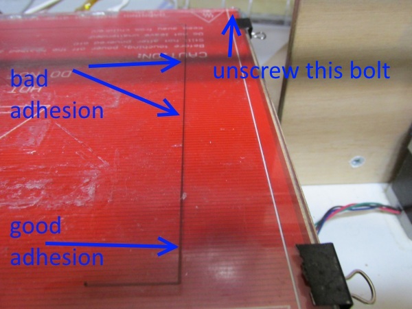
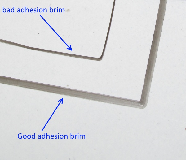
Once you see this effect press "Kill Job" adjust the screw and retest.
You need to adjust the four bolts.
In this case we need to unscrew the top right bolt.
Unscrew at most half turn the bolt each time and retest.
This procedure should take 4/5 attempts.
Using this method you can fine tune the heat bed.
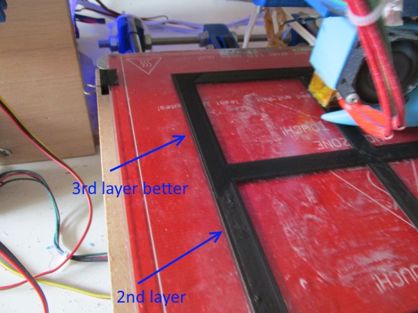
The first layer is crucial (20min). Your first layer may have some inconsistencies like the photo below.
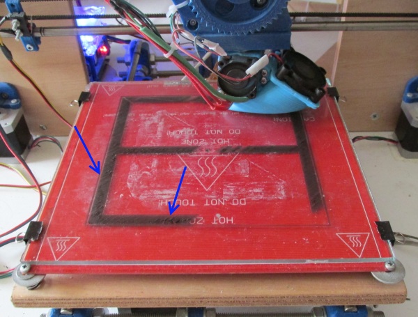
From the third layer you should get a better result.
While printing check specially the angles for warping.
The warping below is "fake" just to show you how it looks like ;)
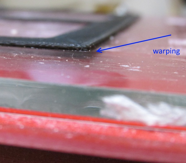
If you get warping add more glue and as last try set the heatbed at 40 degrees but not more than that.
Specially for PLA i do not get any warping issues using 30 degrees at heatbed and stick glue.
Below you can see the hole object printed.
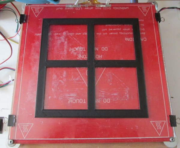
Remove the glass and then remove the printed object.
---Final Axis Calibration---
Now we can calibrate our x-steps using "03-X-Axis-100mm-Thick-10mm.stl"
The printed bar should have 100mm length.
Use these settings :
10% infill
normal speed
0.4mm layer width
0.2mm layer height
Print the object and let it cool down for an hour.
Write at the bar using a pencil the x-steps used.
Avoid measuring the seam.
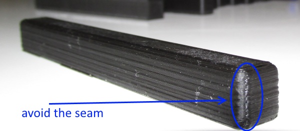
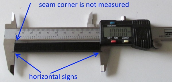
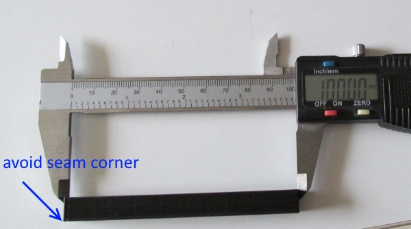
Now use this formula in order to find your new x-steps :
new x_steps = (firmware x_steps * slic3r width)/measured width.
The new value should not be far from 80.00
Now disconnect Repetier-Host go to Arduino IDE and load "Marlin.ino".
Go to "Configuration.h" and change like this :
#define DEFAULT_AXIS_STEPS_PER_UNIT {YOUR_NEW_X_STEPS, 80.00, 4000.00, 878.00}
Save it and press the upload button in order to update the new firmware.
Now re-print the "03-X-Axis-100mm-Thick-10mm.gcode" and re-measure the x-bar.
After finishing the x axis do the same for y and z.
z bar should not have problems with seams and generaly is easier to be measured.
Take your time and print these objects one at a time.
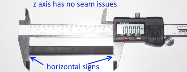
My final axis steps are :
#define DEFAULT_AXIS_STEPS_PER_UNIT {80.14,80.18,4006.00,878.00}
For completion you can now print the "04-Fit-parts-10x6x4mm-0.4mmTol.stl" model.
If you've done the Thin Wall calibration properly, this test should be successful.
Print this object using :
40-60% infill
normal speed
0.4mm layer width
0.2mm layer height
Wait for it to cool off. Try fitting them together.
You should get a tight fit.
If you have problems redo the estep(01 test) and axis tests (03 tests).
This test is only for confirmation purposes.
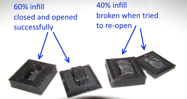
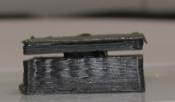
Do not do any firmware modifications based on this object it is only for confirmation purposes.
---Ooze retraction test---
Now it is time to do the "05-ooze_retract_test_by_vector.stl" test.
This is a retraction test. We will see if the extruder gear can work backwords.
Do the test using :
20% infill
normal speed
0.4mm layer width
0.2mm layer height
retraction length : 0.8mm
retraction speed : 60mm/s
For direct hotends 0.6-2mm of retraction is a good range to investigate.
Change the retraction length if you have problems printing this object.
If you have ooze issues then you should increase the retraction length and maybe the retraction speed too.
My values above give to me excellent results.
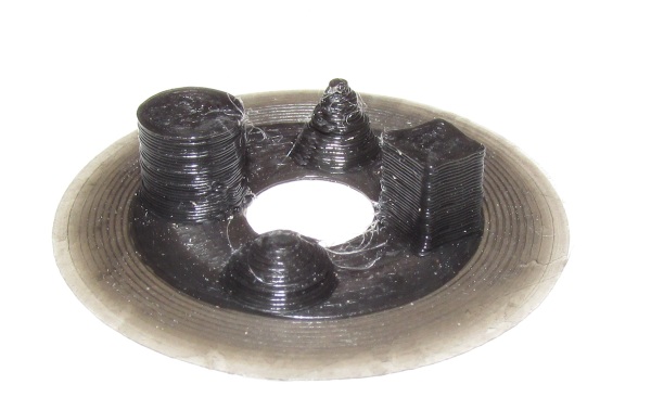
---Bridge test---
Now do the test "06-bridge-torture-test_50mm.stl". This is a 50mm bridge. Do the test using 20% infill
normal speed
bridge Normal speed : 60mm/s
Bridge flow ratio : 1
0.4mm layer width
0.2mm layer height
disable support material
If you have problems you should play with bridge speed and bridge flow ratio.
Adjust your bridge speed by an increment of 10 mm/sec, then print another.
If on bridges your filament doesnt cross the bridge, but breaks mid air, you can increase flow rate for making across the bridge (1.05).
If your bridges sag and too much material is being extruded you can dial it back to have less filament extruded crossing bridges (0.95).
To me the above given values give me pretty good results


---Overhang test---
Overhangs need fan on the nozzle. We will add one at the next section.
Do this test using :
20% infill
normal speed (perimeters 50mm/s)
0.4mm layer width
0.2mm layer height
disable support material
perimeters : 3
Enable auto cooling : true
Slow down if layer print time is below 30(default value) seconds
Min print speed : 10mm/s (default value)
If you have curling problems try :
1) Using a fan on the nozzle (we will see that in the next section)
2) Changing the perimeters speed is an option too (usually lowering the speed 20% down at 40mm/s).
3) Try enabling autocooling at Slic3r with "Slow down if layer print time is below 30"(default value) seconds and "Min print speed" : 10mm/s (default value)
4) Increasing the perimeters to 4
5) Increase your extrusion multiplier by .05 (over extrude)
6) Increase the layer width to 0.5mm.
7) Also lowering the layer height generally improves the overhangs.
Do these variations by changing only one factor at a time. Procede to these changes with the shown order
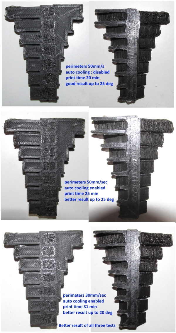
Do not stick on this test too much specially if you do not have any fan at the nozzle.
If you get decent results even at 35 degrees (55 degrees overhang) you are good to go.
Remember the key here is the cooling and slowing down the perimeter speed.
Also notice that you can enable "Generate support material" from "Print settings" > "Support material". Take note that "Overhang threshold" is 45 degrees.
---Overall test---
You can now print an overall test with overhangs / bridges etc ...
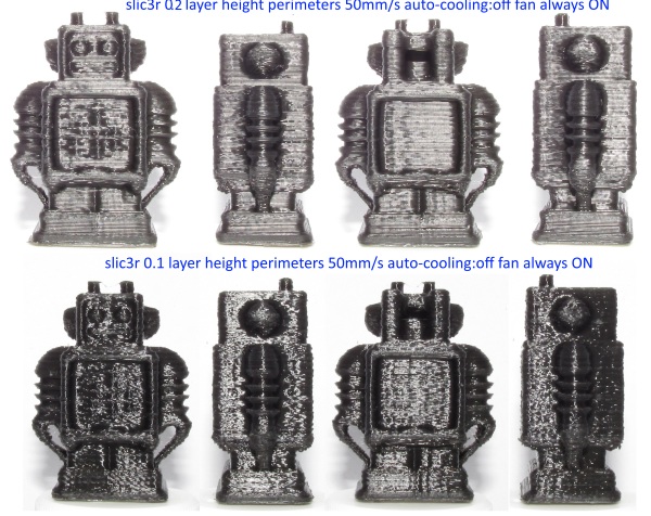
I am using the model "08-UltimakerRobot_support_fixed.stl"
Below you can see some tests using the normal speeds, three perimeters with fan and with auto-cooling disabled.
At 0.1mm layer we can see that the robot becomes more "crystal", indication of overheated PLA.
You may at this point start lowering with PLA temperature and trying again at 195 degrees. Also notice that more cooling is always better.
Not always lowering the layer height increses the quality of print.
The robot took me 20 min at 0.2mm layer height and 40 min at 0.1mm
After doing this set of calibrations you are good to go !
Now you can start printing !
In the next page we will talk about Cura as alternative slicer option.
It is always better having two slicers available in your system.
Section 1 - Wooden frame : part 1 - part 2 - part 3
Section 2 - Y Axis : part 1 - part 2 - part 3
Section 3 - X-Z axis : part 1 - part 2
Section 4 - Extruder : part 1 - part 2 - part 3
Section 5 - Electronics : part 1 - part 2 - part 3
Section 6 - Coarse Calibration & Software : part 1 - part 2 - part 3
Section 7 - Fine Calibration & Software : part 1 - [[ part 2 ]] - part 3
Section 8 - Extras : part 1 - part 2 - part 3
Section 9 - Maintenance & Modding : part 1 - part 2