Constructing a 3D Printer [Prusa I3]
SECTION 1 - Wooden frame - Page 2
Section 1 - Wooden frame : part 1 - [[ part 2 ]] - part 3Section 2 - Y Axis : part 1 - part 2 - part 3
Section 3 - X-Z axis : part 1 - part 2
Section 4 - Extruder : part 1 - part 2 - part 3
Section 5 - Electronics : part 1 - part 2 - part 3
Section 6 - Coarse Calibration & Software : part 1 - part 2 - part 3
Section 7 - Fine Calibration & Software : part 1 - part 2 - part 3
Section 8 - Extras : part 1 - part 2 - part 3
Section 9 - Maintenance & Modding : part 1 - part 2
Place the cut plywood on the table
Firstly glue the bottom frame with the vertical frame like the photos below . Make sure that these two are perpendicular. This is important !
Use the legs for support.
Now wait an hour and then glue the two legs using the 2x2 cm wooden sticks like the photos below:
Use the 2x 41.5cm wooden sticks for the two legs and the 41 cm stick for the top.
Now place some weights and leave the frame to glue overnight.
Remember to also glue the top wooden stick. Look the photo below:
In the meanwhile grab two of your six 2x1 cm wooden sticks and cut them like this :
The other four leave them intact.
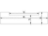
You can use a rasp in order to obdain a polish result.
In newer models i use 10cm 2x1 sticks and not 8cm since it is less probable to split the wood while screwing it down.
Use M3 wood screws to stabilize the hole structure
In particular use 8x M3 wood screws 25 mm length for each leg
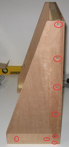
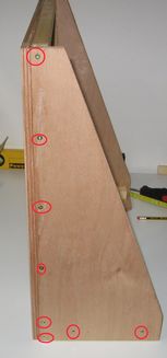
Use 8x M3 wood screws 25 mm length for the front [vertical] panel
The placement of the screws can be found here :
Use 4x M3 wood screws 25 mm length for the bottom panel
Since there was not enough documentation i have lost enough time with the base.
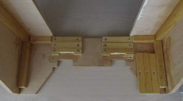
I had to make two 5 x 2,3 cm cuts like the photo below :
These cuts are included at the BottomFrame-LibreCAD.dxf file.
You only need to place the 6 wooden sticks 2x1 cm like the photo below.
The other wooden parts that you see in the photo are not needed.
Use 12 wood screws on order to fix the sticks into the frame base.

Below you can see the base of a new machine using six 2x1 sticks 10cm long.
The finished frame should look something like this :
Another newer machine looks like this :
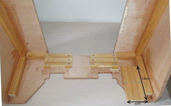
In this machine i also glue down a wooden base 6x13x1cm for ramps (three 2x1 sticks 13 cm long).
Notice that i have added only one woodscrew per stick in the middle in order to screw later RAMPS above this base.
The top part can be seen here :
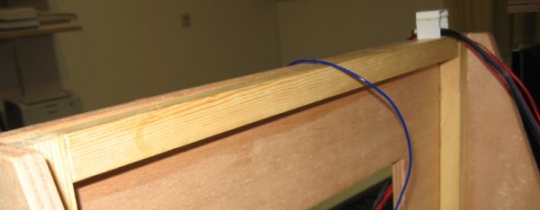
As i said i did not had any documentation for the base so i made it with attempts. But i described above what you have to do.
The right angle :
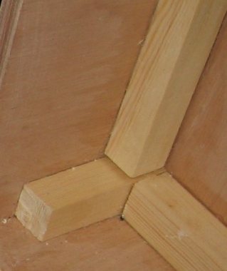
The left angle :
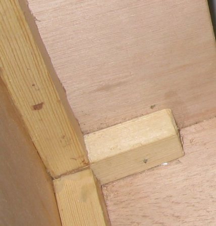
In the next page we will see an alternative way of making the same frame.
Section 1 - Wooden frame : part 1 - [[ part 2 ]] - part 3
Section 2 - Y Axis : part 1 - part 2 - part 3
Section 3 - X-Z axis : part 1 - part 2
Section 4 - Extruder : part 1 - part 2 - part 3
Section 5 - Electronics : part 1 - part 2 - part 3
Section 6 - Coarse Calibration & Software : part 1 - part 2 - part 3
Section 7 - Fine Calibration & Software : part 1 - part 2 - part 3
Section 8 - Extras : part 1 - part 2 - part 3
Section 9 - Maintenance & Modding : part 1 - part 2