Constructing a 3D Printer [Prusa I3]
SECTION 7 - Fine Calibration & Software - Page 1
Section 1 - Wooden frame : part 1 - part 2 - part 3Section 2 - Y Axis : part 1 - part 2 - part 3
Section 3 - X-Z axis : part 1 - part 2
Section 4 - Extruder : part 1 - part 2 - part 3
Section 5 - Electronics : part 1 - part 2 - part 3
Section 6 - Coarse Calibration & Software : part 1 - part 2 - part 3
Section 7 - Fine Calibration & Software : [[ part 1 ]] - part 2 - part 3
Section 8 - Extras : part 1 - part 2 - part 3
Section 9 - Maintenance & Modding : part 1 - part 2
In this section we will start finetuning our 3D printer.
First of all we have already seen how we can communicate via PC with our machine using Repetier-Host.
We have also seen how to modify and upload our Marlin firmware using Arduino GUI.

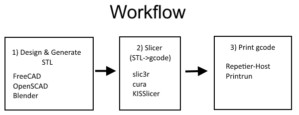
In order to print an object you have to design the model using a CAD tool.
I recommend using FreeCAD [Win,Linux,Mac].
You can also use OpenSCAD [Win,Linux,Mac], Blender [Win,Linux,Mac], Wings3D [Win,Linux,Mac] or Solvespace [Win].
I do NOT recommend SketchUp, specially if you are new, avoid non free tools for commercial use.
Each of these tools saves the model into a propretary file like FCStd for FreeCAD.
All of them export the model into STL (STereoLithography file format) which is needed in order to generate our G-code.
I suggest to start learning a tool for 3D modeling since you will always have to design your own creations.
FreeCAD has a nice wiki with a lot of tutorials.
Once generated the STL file you need to generate the G-code.
G-code is a language in which the user tells to the 3D printer how to print something.
Tools that convert our STL file into G-Code are called slicers.
We will see in this tutorial Slic3r [Win/Linux/Mac] and Cura [Win/Linux/Mac].
There are also others like Slic3r Prusa Edition, ideamaker, CraftWare and KISSlicer.
When we have generated our G-code we can send it to the 3D printer using a printing host program like Repetier-Host [Win/Linux/Mac] or Printrun [Win/Linux/Mac]
In this tutorial we will use Repetier-Host
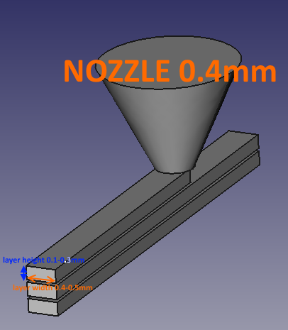
Before start learning about slicers we have to keep in mind our physical limitations for layer height and layer width.
The layer height is the distance the extruder moves between each layer.
Best results are obtained when layer height is between 15-75% of nozzle diameter :
In our case nozzle-diameter = 0.4mm
nozzle-diameter * 0.15 = 0.06mm min layer height
nozzle-diameter * 0.75 = 0.30mm max layer height
Layer width can not be smaller than the nozzle diameter (recommended values : 100% - 125% of the nozzle diameter)
nozzle-diameter * 1.0 = 0.4mm min layer width
nozzle-diameter * 1.25 = 0.5mm normal layer width
In the photo below these limitations are shown in a clear way.
Now that we have clear the terms layer height and layer width we can use slic3r in order to fine tune our printer.
Let's see the settings that slic3r offers and what values we should use.
Run slic3r and go to "File" > "Preferences" > "Mode" : Expert
Slic3r has four sections / tabs : Plater / Print settings / Filament settings / Printer settings.
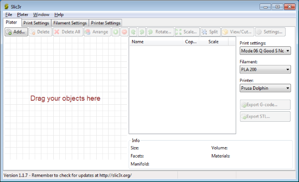
Let's start from the Plater.
From this tab you can load your STL file using the "Add..." button.
You can add more than one STL into a plater. You can also move and rotate your STL's within the plater.
Once you are done you can press the "Export G-code..." in order to generate your G-code file
Before doing this you have to set Print settings / Filament settings / Printer settings.
The plater tab is shown below :
Once we are familiar with the plater let's move on to the "Print settings" tab.
From "Layers and perimeters" we can decide the print quality.
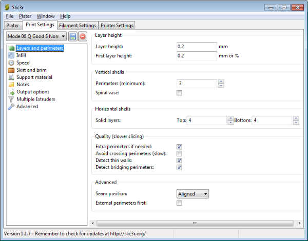
Layer Height : the distance that the extruder moves between each layer.
So, a smaller layer height will generally result in a better quality, smoother part, but will also take longer to print and it will be more fragile.
We already said that valid layer heights for this machine are :
0.06 / 0.08 / 0.1 / 0.12 / 0.14 / 0.16 / 0.18 / 0.2 / 0.22 / 0.24 / 0.26 / 0.28 / 0.30
Normal Quality : 0.24mm
Good Quality : 0.2mm
Better Quality : 0.16mm
Best Quality : 0.1mm
For start use 0.20mm as layer height.
As first layer height use 0.2mm always even if you decide to use layer height = 0.1 for example.
Perimeters (or shells) : a value of 3 here implies that the printer will draw three solid outlines around the edge of the part it's printing, on every layer. In other words Perimeters defines the minimum number of vertical shells/walls. Two is the minimum value, three is the most common/recommended value and four is used for strong parts. Keep in mind that you can combine perimeters and layer thickness in irder to make an object stronger.
Example : Shell thickness (walls) = perimeters * layer width
3 perimeters * 0.5mm layer thickness = 1.5mm shell wall.
Spiral vase : generally keep it unchecked.
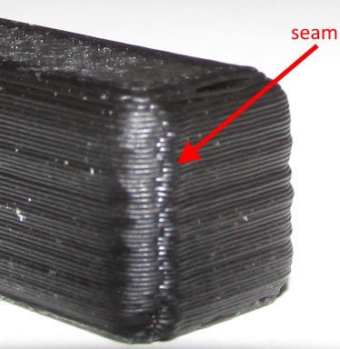
If you ever decide to print a single-walled vase (i.e. with Perimeters set to 1) you can also benefit from the Spiral Vase setting (by enabling it) which will raise Z continuously avoiding a layer-change point which would cause a visible seam like the photo below.
Solid layers : how many solid layers you need on the top of the model and on the bottom of the model.
I generally use and recommend 4 solid layers for top and 4 layers for bottom. (4*0.2=0.8mm solid thickness)
Do not go lower than three specially for the top layer if you use infills at 20% which is a common value.
Using two top layers you are risking to get top holes at your object.
Extra perimeters if needed : yes. This setting adds extra perimeters when you print overhangs (sloped walls)
Avoid crossing perimeters : no. Optimize travel move in order to minimize the crossing of perimeters. This has a negative impact on both G-code generation and print times. It is useful for bowden extruders to fight ooze.
Detect thin walls : yes
This feature checks for collisions between perimeters. It ensures that the printer doesn't try to extrude too close paths, and uses the medial axis algorithm in order to transform thin walls into single-pass extrusions.
Detect bridging perimeters : yes
This option detects the bridging/overhanging portions of perimeters and applies bridge flow/speed to them.
Seam position : aligned
This setting determines the start point of perimeter loops, and thus the position of the potentially visible vertical seam on the side of the object.
The available options are:
Random : This will choose a different point for each layer, thus making the seam less noticeable.
Nearest : This will try to choose a concave non-overhang vertex so that the seam is hidden in the inside of the concave angle. If no concave non-overhang vertices are available, it will choose a convex non-overhang vertex. If none are available, it will choose a non-overhang vertex. The choice among the candidates is operated so that the start point is the nearest to the previous extruder position. So this option will optimize for short travels.
Aligned : This will use the same logic as Nearest for finding the candidates, but it will choose the one that is nearest to the start point of the previous layer. This will ensure the seam is mostly aligned throughout the whole object.
External perimeters first : no.
If enabled prints contour perimeters from the outermost to innermost. (Not recommended in most cases).
By enabling this option makes sure you have geometrically correct dimensions but you are also getting the ending Z-seam outside of the object which will be more visible.
By disabling this option, so that you printing from the inside out, will help anchor your topmost layer to the layer underneath as you print (better option for overhangs).
Once disabled : external perimeter isn't put down before that inner perimeter is laid, allowing for some structure to hang on to.
Also by disabing "External perimeters first" you are also hiding the Z-seam into the inside of the object.
Now let's move on to the Infill category.
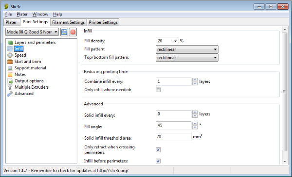
Infill density : 20%.
Is the percentage of each layer that will be filled in with plastic.
A 20% value is the most common value.
You shouldn't have to go above 60% for any reason, unless you want a really dense part.
A density of 0% will only print the perimeter(s) of your part, so it will be completely hollow.
Fill pattern: rectilinear.
Is the path that the extruder takes when doing the infill.
Avoid line infill since produces too weak objects.
Honeycomb stress the machine and produces more noise. I have found that the rectilinear infill is the best overall setting.
Top / Bottom fill pattern : rectilinear
Is the path that the extruder takes when doing the infill for the top and bottom layers.
Use the same setting as above.
Combine infill every 1 layer.
If you are printing with low layer heights like 0.1mm then you can speed up your print by using this setting. If you set is every two layers then the infill layer height will be 2*0.1mm= 0.2mm layer height. Most common value is one and max value would be 3 for layer heights below 0.1mm !
Only infill when needed : no.
Slic3r will analyse the model and choose where infill is required in order to support internal ceilings and overhangs. Useful for reducing time and materials.
Solid infill every : 0 layers.
Solid infill every n layers - Forces a solid fill pattern on the specified layers. Zero will disable this option.
Fill angle : 45° The angle of the infill pattern.
The 45° is the best overall setting.
Solid infill threshold area : 70 mm2
Small areas within the model are usually best off being filled completely to provide structural integrity. This will however take more time and material, and can result in parts being unnecessarily solid. Adjust this option to balance these needs.
Only retract when crossing perimeters yes.
Retracting, to prevent ooze, is unnecessary if the extruder remains within the boundaries of the model.
Infill before perimeters : yes. Reverses the order in which the layer is printed.
I have found that this option should be enabled specially for overhangs.
What this setting does is to prevent a large overhang from placing a perimeter in mid-air, without first connecting it to solid ground with the infill.
We move on to the Speed category.
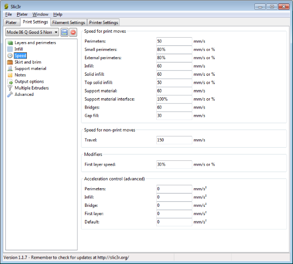
Perimeters : 50mm/s
Speed for contours/vertical shells/walls. This is the most important speed value.
All the other speeds can be defined using this speed value.
Slow speed : 30mm/s
Normal speed : 50mm/s
Fast speed : 60mm/s
Small perimeters : 80% ( 50mm/s (perimeters speed) * 0.8 = 40mm/s )
The speed for holes that have radius <= 6.5mm
Slow speed : 30mm/s
Normal speed : 80% => 50mm/s (perimeters speed) * 0.8 = 40mm/s
Fast speed : 45mm/s
External perimeters 80%
Usually use the same speed as the small perimeters. Affects the visible perimeters.
Slow speed : 70% => 30mm/s (perimeters speed) * 0.7 = 21mm/s
Normal speed : 80% => 50mm/s (perimeters speed) * 0.8 = 40mm/s
Fast speed : 40mm/s
Infill : 60mm/s
The speed of the infill pattern. Set it as fast as you can without compromising the integrity of the fill structure. 60mm/s is a good normal speed.
Slow speed : 60mm/s
Normal speed : 60mm/s
Fast speed : 70mm/s
Solid infill : 60mm/s
Speed for printing solid regions. Usually set it at the same speed as the infill speed above.
Slow speed : 60mm/s
Normal speed : 60mm/s
Fast speed : 70mm/s
Top solid infill : 50mm/s
The speed of the uppermost top visible layer. Slow down in order to get a better and more smooth finish.
Slow speed : 50mm/s
Normal speed : 50mm/s
Fast speed : 50mm/s
Support material : 60mm/s
Generally support structures are quick and dirty, and so long as the base is adequately supported they can be built as quickly as they can. Usually i set the same speed as the perimeters.
Slow speed : 60mm/s
Normal speed : 60mm/s
Fast speed : 70mm/s
Bridges : 60mm/s
The speed for bridges. I have noticed that a good overall value of 60mm/s is ok.
Going too slow will result in sagging, too fast will result in broken strands. Experimentation is the key here.
Slow speed : 60mm/s
Normal speed : 60mm/s
Fast speed : 70mm/s
Gap fill : 30mm/s
Speed for filling gaps. Use a slow speed like 30mm/s to avoid shaking and resonance issues
Slow speed : 20mm/s
Normal speed : 30mm/s
Fast speed : 60mm/s
Travel : 150mm/s
Speed for non printing moves of nozzle. Jumps between distant extrusion points.
Slow speed : 130mm/s
Normal speed : 150mm/s
Fast speed : 180mm/s
First layer speed : 30%( 50mm/s (perimeters speed) * 0.3 = 15mm/s )
Speed for the first layer.
Good values range : 20%-50%
Keep this value slow i use 30% for better adhesion with the heatbed.
Slow speed : 30% (30*0.3=9mm/s)
Normal speed : 30% (50*0.3=15mm/s)
Fast speed : 30% (60*0.3=18mm/s)
In some rare cases i have noticed that i got clogging at first layer using 30% as first layer speed.
If your extruder stops extruding material at first layer and you are pretty sure that the heat-bed is leveled and your extruder is good, set this value at 50% and try again.
Using 50% as first layer speed make sure you have added more glue to your heatbed.
Acceleration control
Leave all these values to 0 in order to ignore them.
Use the Marlin firmware in order to control the acceleration.
Time to move on Skin and Brim.
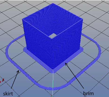
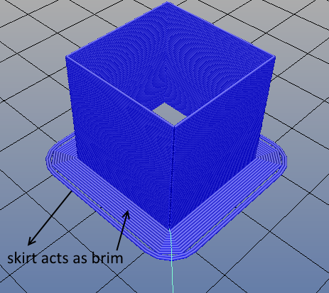
Skirt and brim are indicated in the picture below.
Skirt is used in order to clean the nozzle before start printing and brim is used in order to add adhesion with the bed.
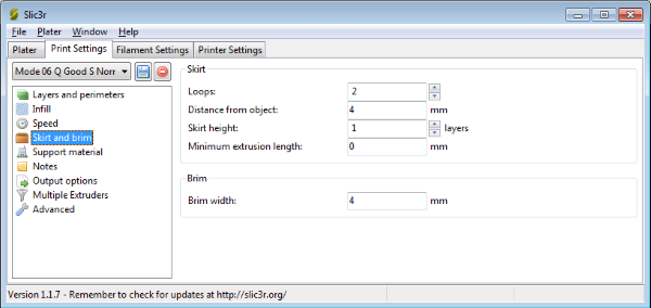
Skirt settings
Loops : How many circuits should be completed before starting on the model.
Two loops are usually sufficient.
Distance from object : The millimeters between the object and the skirt.
4mm is usually sufficient.
Skirt height : The number of layers to lay down a skirt for.
For ensuring the material is flowing smoothly, one layer is sufficient.
Minimum extrusion length : Dictates a minimum number of millimeters that the skirt should be, should the loop around the object not be enough.
A zero value disables this function.
Brim width 4mm
Brim is used to add more perimeters to the first layer, as a base flange, in order to provide more surface area for the print to stick to the bed with in order to reduce warping.
Notice that i use the same value for distance skirt and brim so that the skirt acts as brim.
The next section is the "Support material".
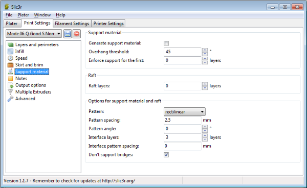
Generate support material : Check it when needed.
This setting will cause your printer to print scaffolding under overhangs and tough angles, giving you better overall results once the support's pulled away.
Overhang threshold : 45 degrees
Is the angle past which support will be generated. To prevent the machine from generating support for tiny protrusions that really don't need it, start with 45 degrees.
You can easily change it to 60 degrees after the overhang test that we will see later.
Enforce support : 0 layers
This option will cause support structures to be printed for the given number of layers, regardless of the overhang threshold angle value.
Raft : 0 layers
Raft will add additional layers underneath the model and stems from the early days of 3D printing.
It can help with prints without a heated bed, or where the bed is not very flat, but it is usually not required and is not recommended. Disable raft use brim instead.
Options for support material
Pattern : rectilinear
The pattern for the support material
Pattern spacing : 2.5 mm
Spacing between support material lines
Pattern angle : 0 degrees
Rotate the support material on the horizontal plane
Interface layers : 3
Number of perpendicular layers between the non-interface support material and the model.
This setting make the support material easier to remove.
Interface pattern spacing : 0mm
This is just like pattern spacing, but for interface layers instead of non-interface layers Set 0 to get a solid interface
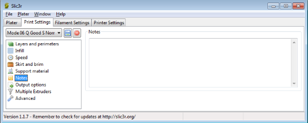
In the next section we see "Notes".
Notes are useful for your own comments, are completely optional, and have no effect on the print. After printing a part and noticing how your changes affected the output, type your comments, measurements and settings in here so you know what to change in the future.
In the next section we see "Output options".
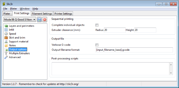
Sequential printing
Complete individual objects : unchecked - change it as you need.
When printing multiple objects this feature will complete each object before moving onto next one and start from it's bottom layer again. This option is helps you to avoid the risk of ruined prints.
Warning : Using this setting you risk for extruder collisions !
Extruder clearence
Radius : 20mm
Set this to the clearence around your extruder
Height : 20mm
The vertical distance between the nozzle tip and the X axis rods, or lowest part which may interfere with a finished print.
Set this to the clearence around your extruder
Height : 20mm
The vertical distance between the nozzle tip and the X axis rods, or lowest part which may interfere with a finished print.
Verbose G-code : no
Generates a commented G-code file.
Not recommended for SD card usage.
Output filename format : [input_filename_base].gcode
You can specify a filename format by using any of the config options.
Just enclose them in square brackets, and Slic3r will replace them upon exporting.
The additional [input_filename] and [input_filename_base] options will be replaced by the input file name (in the second case, the .stl extension will be stripped).
More available variables include [layer_height], [fill_density], [timestamp], [year], [month], [day], [hour], [minute], [second], [version].
The default format is [input_filename_base].gcode, meaning that if you slice a "test.stl" file, the output will be saved to "test.gcode".
Some examples :
[input_filename_base]_h[layer_height]_p[perimeters].gcode
[input_filename_base]_h[layer_height]_p[perimeters]_d[fill_density].gcode
Post processing scripts : empty.
Add a post processing script at your generated G-code.
Now let's see "Multiple extruders" :
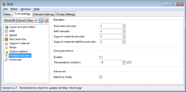
Our machine is single extruder so put 1 into all extruders voices.
Perimeter extruder : 1
Infill extruder : 1
Support material extruder : 1
Support material interface extruder : 1
Ooze prevention : disabled
This option will drop the temperature of the inactive extruders to prevent oozing.
Temperature variation : -5
Difference to be applied when an extruder is not active -5 degrees
Interface shells : false
Force the generation of solid shells between adjacent materials. Useful for two traslucent materials.
In the last section we have the "Advanced" voice.
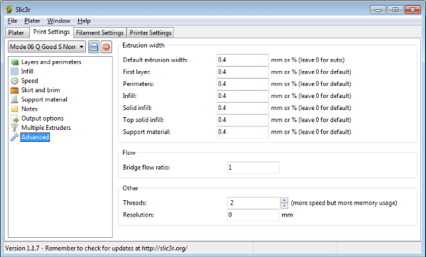
As we already said layer width can not be smaller than the nozzle diameter (recommended values : 100% - 125% of the nozzle diameter)
nozzle-diameter * 1.0 = 0.4mm min layer width
nozzle-diameter * 1.25 = 0.5mm normal layer width
As default extruder width give 0.4mm to all the values for now.
First layer 0.4mm
Perimeters 0.4mm
Infill : 0.4mm
Solid infill : 0.4mm
Top solid infill : 0.4mm
Support material : 0.4mm
You can use 0.5mm layer widths for more robust but less elegant objects .
Bridge flow ratio : 1
Controls how much material is extruded while traveling bridges.
Reducing this slightly (0.95) can help bridging by stretching the filament more.
If on bridges your filament doesnt cross the bridge, but breaks mid air, you can increase flow rate for making across the bridge (1.05).
If your bridges sag and too much material is being extruded you can dial it back to have less filament extruded crossing bridges (0.95).
Using a fan can also help.
Threads : 2
Threads are used to paralellize long tasks.
More threads consume more memory.
If you have a dual core or more CPU use two threads. Resolution : 0 (disabled)
Resolution will perform a simplification on the XY plane after the model is sliced.
You can set the resolution option to a value like 0.01mm.
If you leave resolution to zero, no simplification will happen in Slic3r and the output G-code will reflect the full resolution of the original model.
Before moving into the next tab save your "Print settings" using the save button
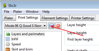
The next tab is the "Filament settings"
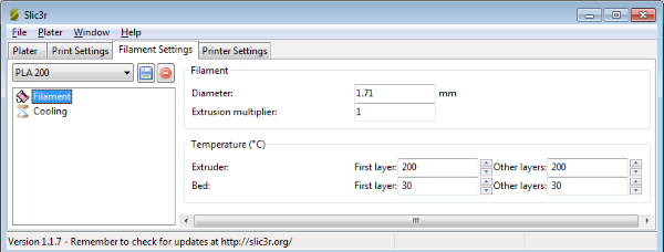
Measure your filament like the photo below.
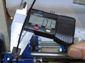
Use a caliper and take several measurements in different lengths.
I usually get 1.71mm average filament diameter.
Diameter : 1.71mm
Extrusion multiplier : 1
The Extrusion multiplier = slic3r layer width/measured width.
This value effects the e-steps.
Instead using this value it is better to finetune your e-steps. We will see how in the next page.
For small changes on extruder steps you can slightly change this value. (In overhangs is useful adjusting this value to 1.05 over-extrude)
Temperature :
Extruder 200°C for PLA (minimum 190°C better value at summer - maximum 200°C better value at winter )
Bed : 30°C for PLA
Use the same values for first and other layers.
Under the voice "Cooling" :
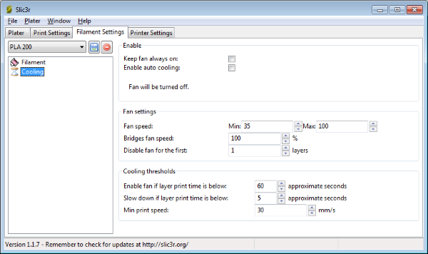
Our 3D printer does not control the fan.
At the 8th section of our tutorial we will add a fan on the extruder. The installed fan will be constantly plugged to our power supply.
Keep fan always on : disabled
In our case this setting does not do anything since we have constatly plugged the fan into the power supply.
Enable auto cooling : (disabled : in most cases if you have a fan / enabled : if you do not have a fan or do bridges/overhangs).
If auto cooling is enabled then the "Cooling thresholds" are active.
Enable fan if layer print time is below 60 seconds
Indifferent in our case.
Slow down if layer print time is below 5(good value if you have a fan) / 30(default value) seconds
Useful in our case if autocooling is enabled.
Min print speed : 30mm/s(good value if you have a fan) / 10mm/s (default value)
Useful in our case if autocooling is enabled.
Notice that "Slow down if layer print time is below" and "Min print speed" affect heavily the print time of an object.
I recommend the default values (30s / 10mm/s) if you are not using fan at all.
As we will see at the 8th section of our tutorial we will add a constant fan so we are going to set (5s / 30mm/s) which will lower a lot the print time of the machine.
Also by adding a fan into the extruder the "Enable auto cooling" can be disabled most of the times.
By disabling "Enable auto cooling" all the "Cooling thresholds" limitations are ignored.
Fan settings :
Ignore these values for our machine by letting them to their default values.
Fan speed Min 35% - Max 100% (default values)
Bridges fan speed 100% (default)
Disable fan for the first 1 layer (default).
Before moving into the next tab save your "Filament" using the save button
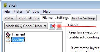
Now let's move on to the fourth and final tab.
Printer settings
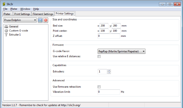
Under the general voice :
Bed : X : 200 / Y : 200 mm
Print center X : 100 / Y : 100
Z offset : 0mm
G-code favor : Marlin
Use relative E distances : disabled
Extruders : 1
Use firmware retraction : no
Vibration limit : 0 Hz
Under Custom G-code :
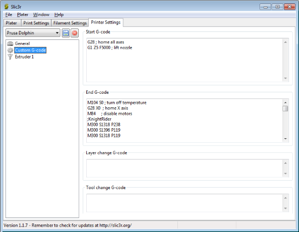
In the 8th section we will add a RepRapDiscount Smart Controller.
This controller support printing directly from SD cards and can play sounds.
We can play a ringtone once the print is ended.
For now we will add the ringtone at the "End G-code section".
Start G-code :
G28 ; home all axes
G1 Z5 F5000 ; lift nozzle
End G-code :
M104 S0 ; turn off head
M140 S0 ; turn off bed
G91 ; relative movements
G1 Z5 ; Z up 5mm
G90 ; back to absolute
G28 X0 ; home X axis
G28 Y0 ; home Y axis
G1 Y200 ; Move Y axis at 200
M84     ; disable motors
;KnightRider
M300 S1318 P238
M300 S1396 P119
M300 S1318 P119
M300 S987 P476
M300 S2637 P238
M300 S2793 P119
M300 S2637 P119
M300 S987 P476
M300 S1318 P238
M300 S1396 P119
M300 S1318 P119
M300 S987 P238
M300 S2637 P238
M300 S2349 P952
M300 S0 P476
M300 S0 P952
M300 S1318 P238
M300 S1396 P119
M300 S1318 P119
M300 S987 P476
M300 S2637 P238
M300 S2793 P119
M300 S2637 P119
M300 S987 P476
M300 S1318 P238
M300 S1396 P119
M300 S1318 P119
M300 S987 P238
M300 S2637 P238
M300 S2793 P952
M300 S0 P952
More ringtones can be found here (RTTTL ringtones) and can be convered in gcode using this web page (RTTTL to gcode online tool).
I use the KnightRider ringtone because it is long and is loud enough.
Another good option is this ringtone below :
;Blue (Da Ba Dee)
M300 S880 P214
M300 S932 P214
M300 S1174 P214
M300 S1567 P214
M300 S932 P214
M300 S2093 P214
M300 S1396 P214
M300 S880 P214
M300 S932 P428
M300 S1567 P214
M300 S932 P214
M300 S2349 P214
M300 S2489 P214
M300 S1567 P214
M300 S2349 P214
M300 S2093 P214
M300 S932 P214
M300 S1174 P214
M300 S1567 P214
M300 S932 P214
M300 S2093 P214
M300 S1396 P214
M300 S880 P214
M300 S932 P428
M300 S1567 P214
M300 S932 P214
M300 S2349 P214
M300 S2489 P214
M300 S1567 P214
M300 S2349 P214
M300 S2093 P214
M300 S932 P214
M300 S1174 P214
M300 S1567 P214
M300 S932 P214
M300 S2093 P214
M300 S1396 P214
M300 S880 P214
M300 S932 P428
M300 S1567 P214
M300 S932 P214
M300 S2349 P214
M300 S2489 P214
M300 S1567 P214
M300 S2349 P214
M300 S2093 P214
M300 S932 P214
M300 S1174 P214
M300 S1567 P214
M300 S932 P214
M300 S880 P214
M300 S1046 P214
M300 S1396 P214
M300 S1567 P857
Under "After layer change G-code" write
; LAYER: [layer_num], Z HEIGHT: [layer_z]
By adding this setting your generated g-code is more readable using a normal text editor like notepad++
Every time that a layer changes you get useful comments into the generated gcode file.
For example :
G1 Z13.400 F9000.000
; LAYER: 66, Z HEIGHT: 13.4
; PURGING FINISHED
G1 X108.943 Y108.006
G1 E0.40000 F3600.00000
So ,for example, if you want to change filament color (multicolor print using a single hotend) you can simply add by hand the M600 command like this :
G1 Z13.400 F9000.000
; LAYER: 66, Z HEIGHT: 13.4
; PURGING FINISHED
M600
G1 X108.943 Y108.006
G1 E0.40000 F3600.00000
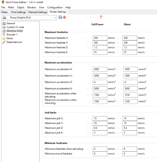
Newer versions of Slic3r made by Prusa (Slic3r Prusa Edition) include the voice : "Machine limits"
For our project machine fill like this :
Time to move on to the last voice "Extruder 1"
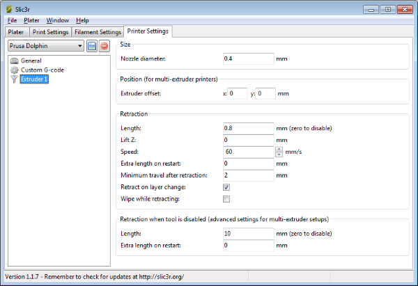
Nozzle diameter : Place your nozzle diameter of your extruder. Our is 0.4 mm
Extruder offset X : 0mm / Y : 0mm
Retraction length : 0.8mm (a good value to start)
Retraction will greatly improve the quality of your prints.
By retracting the hot filament with the extruder motor during travel moves, plastic oozing is prevented.
For direct hotends 0.20-2mm of retraction is a good range to investigate.
For bowden printers you have to use 1-6mm instead.
Note that the measurement is taken from the raw filament entering the extruder.
This value need to be lower at summer and bigger at winter.
Lift Z : 0mm
Lift Z will raise the extruder during retraction and before moving to the next path, where it will lower, in order to avoid knocking the part off the platform or dragging plastic with it.
Disable this option by setting it to 0.
Speed : 60mm/s
How quickly your extruder motor will reverse to retract the filament.
You want this to be quick, so do some tests with your extruder and see just how fast you can retract. A 60 mm/s is our recommended value.
Extra length on restart : 0mm
Adds an extra length of filament after the retraction is compensated after the travel move.
This setting is rarely used, however should the print show signs of not having enough material after travel moves then it may be useful to add a small amount of additional material.
Minimum travel after retraction : 2mm
Retraction is not triggered when travel moves are shorter than this length.
Triggering a retraction after very short moves is usually unnecessary as the amount of ooze is usually insignificant and it slows down the print times.
Set the number of millimeters minimum distance the nozzle must move before considering a retraction.
If the printer handles ooze well this can be increased to 5 or 6mm.
Retract on layer change : true
This is an important setting. Let it on since it prevents oozing while the layer changes.
Wipe before retract : disable
Moves the nozzle whilst retracting so as to reduce the chances of a blob forming.
Avoid using this setting it is reccomended on really old extruder models.
Retraction when tool is disabled (advanced settings for multi extruder setups)
These settings are not used in our case so leave them at their default values
Length : 10mm
Extra length on restart : 0mm
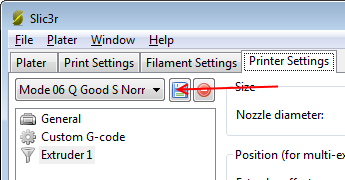
Now save your printer settings :
In the next page we will see how we can finally finetune our 3D printer using the configured Slic3r.
Section 1 - Wooden frame : part 1 - part 2 - part 3
Section 2 - Y Axis : part 1 - part 2 - part 3
Section 3 - X-Z axis : part 1 - part 2
Section 4 - Extruder : part 1 - part 2 - part 3
Section 5 - Electronics : part 1 - part 2 - part 3
Section 6 - Coarse Calibration & Software : part 1 - part 2 - part 3
Section 7 - Fine Calibration & Software : [[ part 1 ]] - part 2 - part 3
Section 8 - Extras : part 1 - part 2 - part 3
Section 9 - Maintenance & Modding : part 1 - part 2