Constructing a 3D Printer [Prusa I3]
SECTION 3 - X Z axis - Page 2
Section 1 - Wooden frame : part 1 - part 2 - part 3Section 2 - Y Axis : part 1 - part 2 - part 3
Section 3 - X-Z axis : part 1 - [[ part 2 ]]
Section 4 - Extruder : part 1 - part 2 - part 3
Section 5 - Electronics : part 1 - part 2 - part 3
Section 6 - Coarse Calibration & Software : part 1 - part 2 - part 3
Section 7 - Fine Calibration & Software : part 1 - part 2 - part 3
Section 8 - Extras : part 1 - part 2 - part 3
Section 9 - Maintenance & Modding : part 1 - part 2
Place the X-Z frame to the wooden frame.
Fix the "z axis top" part 2,5 cm from the top like the photo below and fix it with a M10 20 mm screw.
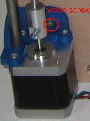
Now screw the three wood screws like the photos below.

Repeat the process on the other side of the z axis.
You have to use eight wood screws for this step.
It is now time to level really well the X level horizontally.
Screw / Unscrew the left or the right M5 threaded rod by hand to obtain a horizontal x axis. Here is the hole structure after leveling the X axis
Now pass the GT2 belt starting from the "x arm".
Insert the "x arm" back into it's place and use a M3 30 mm bolt and a nut in order to keep the arm into place
Pass the belt from the pulley.
Pass the belt from the "x carriage".
Use a couple of zip ties in order to secure the belt.
Do the same in the other part
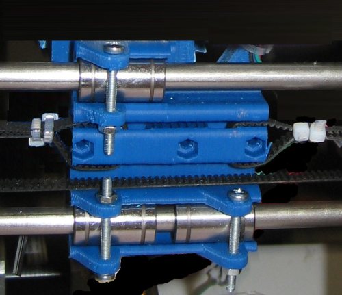
The final result of the "x carriage"

Using the indicated screw you can tight the belt.
As we did with the y axis we repeat the process for our two (x,z) endstops.
Enlarge the two holes of each mechanical endstop using a 3 mm drill bit.
Create a new hole for the endstop handle and cut the handle at the red line.
This is not needed with the new "x-z-endstop-holder.stl". Just use the two holes.
Solder the two endstops with the endstop cable like the photos below :
The yellow wire is not needed [optical endstop] just isolate it.
Pay attention at the polarity of the cables. Black-front, Red-back.


Now we have to place the X and Z endstops.
The X endstop :
The Z endstop :
We are done !
Again make sure that you do not fix the Y axis made into the section 2 with the frame.
The next section is the extruder part.
Section 1 - Wooden frame : part 1 - part 2 - part 3
Section 2 - Y Axis : part 1 - part 2 - part 3
Section 3 - X-Z axis : part 1 - [[ part 2 ]]
Section 4 - Extruder : part 1 - part 2 - part 3
Section 5 - Electronics : part 1 - part 2 - part 3
Section 6 - Coarse Calibration & Software : part 1 - part 2 - part 3
Section 7 - Fine Calibration & Software : part 1 - part 2 - part 3
Section 8 - Extras : part 1 - part 2 - part 3
Section 9 - Maintenance & Modding : part 1 - part 2