Constructing a 3D Printer [Prusa I3]
SECTION 8 - Extras - Page 1
Section 1 - Wooden frame : part 1 - part 2 - part 3Section 2 - Y Axis : part 1 - part 2 - part 3
Section 3 - X-Z axis : part 1 - part 2
Section 4 - Extruder : part 1 - part 2 - part 3
Section 5 - Electronics : part 1 - part 2 - part 3
Section 6 - Coarse Calibration & Software : part 1 - part 2 - part 3
Section 7 - Fine Calibration & Software : part 1 - part 2 - part 3
Section 8 - Extras : [[ part 1 ]] - part 2 - part 3
Section 9 - Maintenance & Modding : part 1 - part 2
In this section we will try to construct few important extra parts for your 3D printer.
1) Spool holder
This kind of spool holder is cheap to make and it is placed "inside" the machine so it does not occupy extra space. We are going to add a spool holder for our machine.
The spool holder stl files can be downloaded from here.
I have also included this item at thingiverse.com
You should print two times the sh-round.stl at 20% infill and one time the sh-arm.stl at 60% infill.
We also need six M10 bolts, two M10 washers and a M10 rod 20cm long.
If you followed our tutorial the y axis has been made using two 40cm M10 rods.
Usually the M10 rods are sold by meter, so you should have a remaining 20 cm piece laying around.
Below you can see the extra metal items you should get in order to make the spool holder.

Now add some electrical tape at two of the six M10 nuts like the picture below :

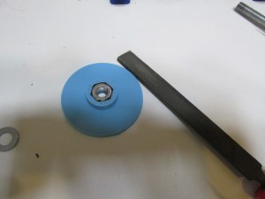
Add the M10 nut at the "sh-round.stl". File the nut to remove the excess tape like the pictures below .
Repeat the processs at both of "sh-round.stl"


Now place the "sh-arm.stl" at the right leg of the machine like the picture below
Use four wood screws in order to firm securely the arm on the wooden frame.
The arm should distance 6cm from the top and 4 cm from the front face.

Pass the M10 rod from the arm and using two m10 washers and two nuts block the rod with the arm.

Pass a new M10 (third) nut at the rod like the photo below

Now pass the "sh-round.stl" with the embedded nut and block it with the third nut.

Now load the PLA 1kg spool.


Now pass the second "sh-round.stl" and block it with the nut.
Leave at least 1 cm between PLA spool and "sh-round.stl". The spool should roll freely.


Final assembly :

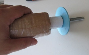
For better results i have made a dual cilinder.
The inner cilinder was made using normal A4 papper starting from 10mm diameter and reaching the 28mm of diameter. I have used 10 A4 sheets folded in half along the longer dimension of the paper.
It's height is 95mm.
Once made this white internal cilinder i have used packing tape in order to fix it.
The outer cilinder was made by cardboard from 28mm diameter to 55mm of diameter.
The height is always 95mm.
Again crystal tape was used in order to fix the outer cilinder.
The two cilinders can slide one inside the other.
Below you can see some pictures of the dual cilinders.


By doing the two papper cilinders you can use the inner one for the older Chinese white PLA spools and both cilinders in order to mount the newer crystal Real PLA spools like the photo below.

In the next page we will see how we can add a fan into our nozzle in order to improve the printing quality.
Section 1 - Wooden frame : part 1 - part 2 - part 3
Section 2 - Y Axis : part 1 - part 2 - part 3
Section 3 - X-Z axis : part 1 - part 2
Section 4 - Extruder : part 1 - part 2 - part 3
Section 5 - Electronics : part 1 - part 2 - part 3
Section 6 - Coarse Calibration & Software : part 1 - part 2 - part 3
Section 7 - Fine Calibration & Software : part 1 - part 2 - part 3
Section 8 - Extras : [[ part 1 ]] - part 2 - part 3
Section 9 - Maintenance & Modding : part 1 - part 2