Constructing a 3D Printer [Prusa I3]
SECTION 9 - Maintain & Modding - Page 2
Section 1 - Wooden frame : part 1 - part 2 - part 3Section 2 - Y Axis : part 1 - part 2 - part 3
Section 3 - X-Z axis : part 1 - part 2
Section 4 - Extruder : part 1 - part 2 - part 3
Section 5 - Electronics : part 1 - part 2 - part 3
Section 6 - Coarse Calibration & Software : part 1 - part 2 - part 3
Section 7 - Fine Calibration & Software : part 1 - part 2 - part 3
Section 8 - Extras : part 1 - part 2 - part 3
Section 9 - Maintenance & Modding : part 1 - [[ part 2 ]]
Prusa i3 can be heavily modded. Here we will see some hacking ideas.
1) Fold-able frame
If you want to make your printer more mobile/portable you can fold it easily by using the y-ancor stl (alternative link: thingiverse thing:1130738).
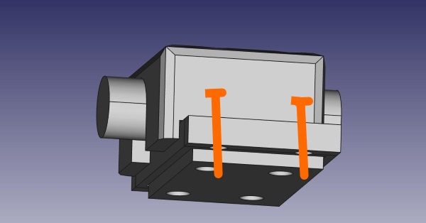
Each bracket contain four M3 nuts.
I have fixed each bracket at the wooden frame using four gold coloured wood M3 screws.
Using this you can separate the y plane from the z/x plane.
You can now fold the printer easily.
If you need to ship a printer within a parcel this saves you a lot of space.
Using some hot glue at the two M10 back nuts you can safely remove the y axis from the rest body without needing recalibrating the machine.
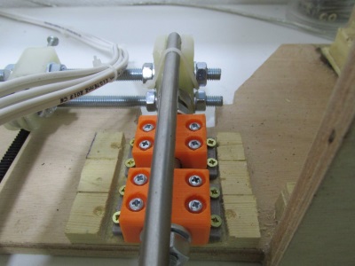
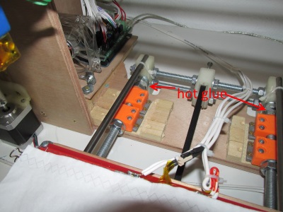
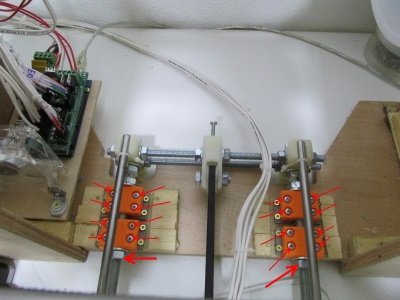
By unscrewing the 16 M3 bolts and the two M10 nuts indicated you can remove the y axis any time you like.
2) Bowden extruder solution
I am not a big fun of bowden solutions.
First of all in order to have a decent bowden solution you have to use almost certainly 3mm filament.
3mm filament will have to be squeezed 7.5 times for a 0.4mm nozzle instead of 4.375 times for a 1.75 filament
Notice that the 1.75 mm filaments have way better resolution that the 3mm ones and are way more common these days.
The bowden stepper motor must be bigger in order to compensate this fact.
The bowden cable system has hysteresis and this will produce the so called oozing effect.
In order to fight this effect you have to play with way higher accelerations than the direct solution.
Many people think that the bowden solution is a quiter solution since the moving parts are less lighter.
This is wrong since you have to accelerate the extruder in order to fight ooze.
Some settings for the slic3r can be found here and here.
Since you are forced to use bigger motor, higher speeds and accelerations will stress the machine a lot more.
Also if you plan on printing with the new soft materials coming out like Flex TPU, ninjaflex or PolyMaker PolyFlex then a direct solution will be way better than a bowden one.
Again notice that with our direct set up you can achieve the bowden speeds even if the head is 500gr.
Download and print these files for a bowden version of an E3D v5 nozzle : extruder-bowden (alternative link: thingiverse thing:1130813).
Below are some photos and files of a third machine of mine using the bowden method.
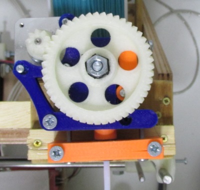
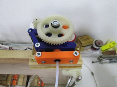
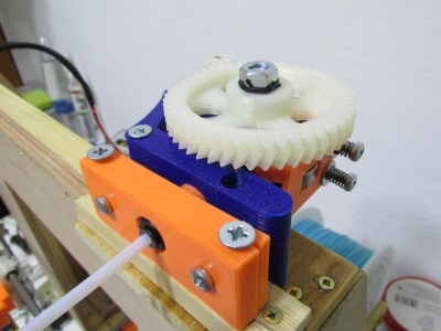
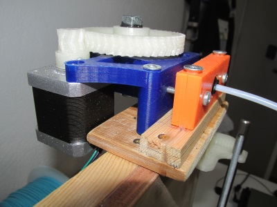
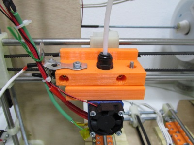
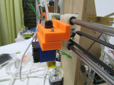
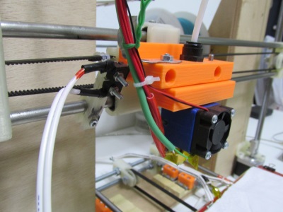
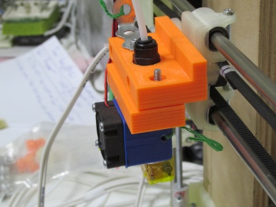
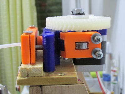
Final result :
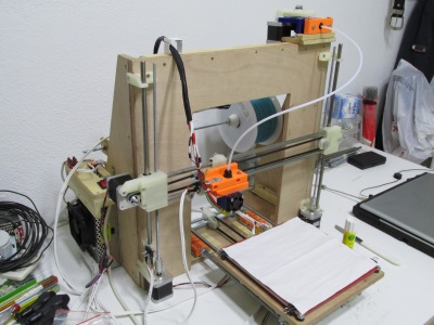
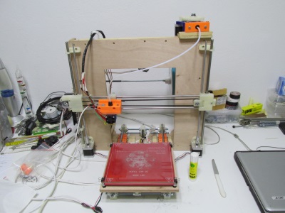
3) Using E1 extruder jack on RAMPS instead of E0
In one of mine printers the RAMPS board arrived broken.
The X, Y axes where poorly soldered and i managed to resolder the cold soldered joints.
I could not find what was wrong with the E0 port even if i knew that the StepStick A4988 driver was working.
With our configuration we are using 4 ports of the 5 available of RAMPS so i placed the extruder driver at the E1 port instead of the E0 port.
I had to edit the pins.h file of the marlin firmware around the 467 line like this :
#define E0_STEP_PIN 36//26
#define E0_DIR_PIN 34//28
#define E0_ENABLE_PIN 30//24
#define E1_STEP_PIN 26//36
#define E1_DIR_PIN 28//34
#define E1_ENABLE_PIN 24//30
In the new marlin version this portion of code can be found around the line 622 of pins.h file.
Once you have changed the file do not forget to save, compile and upload the firmware using arduino GUI.
As you can see i just swapped the pins of the E0 to E1 .
This solution worked great with the defective RAMPS board.
I am still using this RAMPS board for over a year without any further problems.
You can also swap X,Y or Z axes if you have problems with these ports.
With this page we have ended our 3D printer tutorials.
As you can see a lot of other mods can be made and this is the magic of the open hardware world !
Since you have constructed this machine you will realize all the benefits that you have gained from this procedure.
Happy modding !!!
Section 1 - Wooden frame : part 1 - part 2 - part 3
Section 2 - Y Axis : part 1 - part 2 - part 3
Section 3 - X-Z axis : part 1 - part 2
Section 4 - Extruder : part 1 - part 2 - part 3
Section 5 - Electronics : part 1 - part 2 - part 3
Section 6 - Coarse Calibration & Software : part 1 - part 2 - part 3
Section 7 - Fine Calibration & Software : part 1 - part 2 - part 3
Section 8 - Extras : part 1 - part 2 - part 3
Section 9 - Maintenance & Modding : part 1 - [[ part 2 ]]